Solution

LiDAR solutions for UAV terrain following

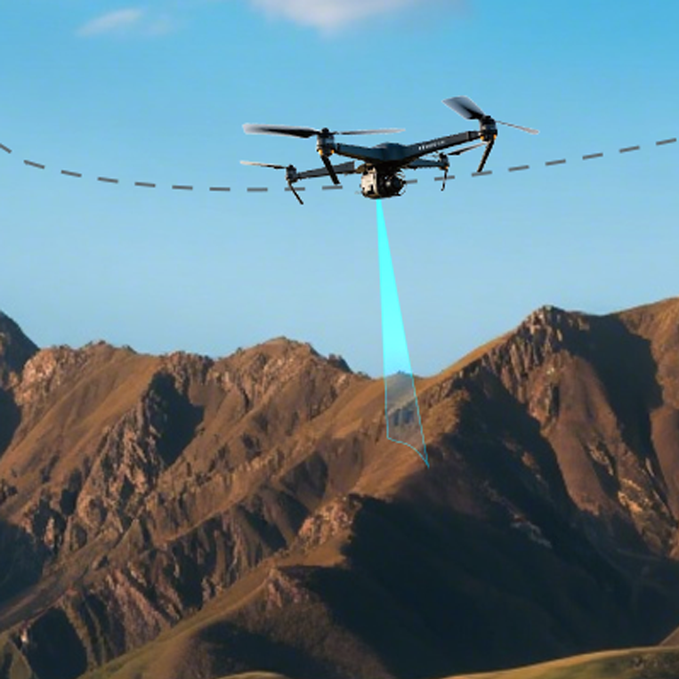
Measure the distance between the aircraft and the surface below, providing continuous range input for low-altitude terrain-following adjustment.

A UAV using downward-facing LiDAR for terrain following over mountainous terrain

Scenario

Maintain target ground clearance over changing surfaces

Agricultural, mapping, inspection, and contour-flight UAVs need ground clearance while terrain, crop canopy, and target surfaces change. The task is not to hold a fixed altitude reference; it is to give the flight controller the actual gap to the current surface below.

The engineering problem

  • A fixed altitude reference does not directly represent the gap to the surface below.
  • Maximum range on a standard target is not the usable range for every field surface.
  • Tilt, vibration, obstruction, and out-of-range data must not enter a control loop unchecked.

Why LiDAR

A single-point ToF LiDAR measures line-of-sight distance to the target below inside its validated range. It provides direct near-ground input, while reflectivity, ambient light, attitude, weather, contamination, and mounting still affect the result.

From ranging to height adjustment

  1. Mount downward and keep landing gear, wiring, and other structures out of the field of view.
  2. Output range through the interface supported by the product.
  3. Configure the target flight stack for the correct port, orientation, and healthy envelope.
  4. Fuse range with attitude and other estimates in the appropriate flight mode.
  5. Define fallback behavior for no return, out-of-range, jumps, and disconnects.
  6. Validate on real surfaces before controlled flight testing.

Technology comparison

DimensionConditionLiDARAlternativeAlternative performanceConclusion
Height referenceLow-altitude flight with downward range inside the field-validated healthy envelope.Direct line-of-sight range to the surface below.GNSS / barometerGlobal or relative altitude reference.

LiDAR adds current ground clearance while GNSS and the barometer provide different state references; they are not simple substitutes.

Official ArduPilot Surface Tracking documentation.ArduPilot Surface Tracking · Verified 2026-08-24

Scroll horizontally to view all columns

Integration

Platform integration resources

9 resources across 2 platforms are linked to this application.

ArduPilot

6 resources

PX4

3 resources

Installation and integration

  • Prefer downward-facing installation, record orientation and mounting height in the airframe frame, and keep landing gear, wiring, and other structures out of the field of view.

    TF-Luna / TFmini-S / TFS20-L / TFA170-L / TF02-Pro / TF03 · UAV airframe · Target vehicle configuration verified before flightArduPilot RangeFinder Setup Overview · Verified 2026-08-24
  • The current ArduPilot Rangefinder list covers the corresponding Benewake driver families. Still verify the exact model, target board, firmware build, port, and interface rather than treating the list as integration without validation.

    TFmini-S / TFS20-L / TF03 · ArduPilot · Target board and firmware build verified before deploymentArduPilot Rangefinders · Verified 2026-08-24
  • Set minimum and maximum healthy range from real-target, attitude, and environmental validation, and define fallback for no return, out-of-range data, jumps, and disconnects.

    TFmini-S / TFS20-L / TFA170-L / TF03 · Flight stack · Healthy range established on the target surface and environmentArduPilot Rangefinders · Verified 2026-08-24
  • Before installation, verify the sensor field of view, ground attitude, power, and interface; validate on the target airframe and configure failure handling.

    TF-Luna / TF02-Pro · UAV airframe · Target vehicle configuration verified before flightTF-Luna and TF02-Pro Datasheets · Verified 2026-09-20

Operating limits

  • The 0.1–12 m range uses a 90% reflectivity target and becomes 0.1–7 m at 10% reflectivity. The current datasheet lists protection as “/”, so outdoor use needs vehicle-level protection.

    TFmini-STFmini-S Datasheet A01 · Verified 2026-08-24
  • The 20 m range uses a 90% reflectivity target at 0 KLux; low reflectivity and 100 KLux reduce range, and the module has no enclosure.

    TFS20-LTFS20-L User Manual · Verified 2026-08-24
  • The 170 m rating uses stated reflectivity conditions. The unenclosed module uses 12 V / RS-232; verify output rate against the delivered document revision.

    TFA170-LTFA170-L Datasheet · Verified 2026-08-24
  • The current product page states 180 m, IP67, and multiple interfaces. Include the approximately 86 g mass and exact interface variant in vehicle and delivery checks.

    TF03TF03 official product page · Verified 2026-08-24
  • LiDAR supplies range input only; trajectory control, fusion, mode changes, fallback, and vehicle safety remain flight-stack and system responsibilities.

    UAV terrain-following solutionArduPilot Surface Tracking · Verified 2026-08-24
  • Effective range for TF-Luna and TF02-Pro depends on target reflectivity, ambient light, attitude, and mounting; validate on the target airframe and configure failure handling.

    TF-Luna / TF02-ProTF-Luna / TF02-Pro Datasheets · Verified 2026-09-20

Sources

Verifiable specification basis

TFmini-S range conditions

The datasheet states range separately for 90% and 10% reflectivity and lists a 5 g mass plus UART, I²C, and I/O. These are sensor specifications, not vehicle-level terrain-following accuracy.

0.1–12 m

25°C standard target; revalidate real ground, ambient light, attitude, and mounting.

TFmini-S Datasheet A01

TFS20-L range conditions

The manual separates range by reflectivity and ambient light and lists an approximately 1.35 g mass, UART/I²C, and no enclosure. Establish the healthy envelope on the real target.

0.2–20 m

Check the stated 90%/10% reflectivity and 0/100 KLux conditions separately.

TFS20-L User Manual

TFA170-L long range and low mass

The datasheet specifies 0.1–170 m on a 90% reflectivity target, an approximately 10 g mass, and RS-232. Recheck revision-sensitive values such as output rate against delivered documentation.

0.1–170 m

Standard-target specification; revalidate the real surface, ambient light, and delivered revision.

TFA170-L Datasheet

TF03 protection and interfaces

The official product page lists 0.1–180 m, IP67, approximately 86 g, and UART, CAN, RS-232, and RS-485. Confirm the exact interface variant and field envelope before delivery.

0.1–180 m

Current product-page revision; validate the target surface, environment, and delivered variant.

TF03 official product page

FAQ

Frequently asked questions

Can LiDAR alone guarantee safe terrain-following flight?

No. LiDAR supplies range to the surface below. Attitude compensation, fusion, control, mode transitions, and fallback belong to the flight stack and vehicle system.

Resources

Resources and references

Confirm the selection with real mission conditions

Share the operating height, target surface, environment, mounting space, and flight-stack version. Our engineering team can help plan selection and validation.

Talk to an engineer

Product inquiry

Talk to a product specialist

Tell us what you need and our team will get back to you.

Product inquiry

Inquiry sent

Your inquiry has been received. We will be in touch soon.