
Technical documents
TFS20-L User Manual
This manual covers the measuring principle, technical specifications, hardware interface, and configuration of the TFS20-L LiDAR. Please read carefully before use to ensure proper
This manual covers the measuring principle, technical specifications, hardware interface, and configuration of the TFS20-L LiDAR. Please read carefully before use to ensure proper operation and avoid damage.
1. Product Overview
The TFS20-L is a miniaturized single-point LiDAR module based on direct Time of Flight (dToF) technology. The laser at the transmitting end collimates and emits a pulsed laser signal through the transmitting lens. After reflection by the measured object, the echo signal enters the receiving lens and is detected by a high-sensitivity SPAD detector. The distance is calculated based on the time difference between transmission and echo signals and the speed of light.
1.2 Technical Specifications
| Performance Parameter | Value |
|---|---|
| Detection Range | 0.2-20m@90% reflectivity@0Klux, 0.2-15m@90% reflectivity@100Klux0.2-12m@10% reflectivity@0Klux, 0.2-9m@10% reflectivity@100Klux |
| Accuracy① | ±6cm (0.2~6m), 1% (≥6m) |
| Repeatability② | 2cm (0.2~6m) @1σ |
| Frame rate | 0/ 20 / 50 / 100 (default) / 250Hz |
| Ambient light resistance | 100KLux |
| Parameter | Value |
|---|---|
| Light source | VCSEL |
| Central wavelength | 905nm |
| FoV | <2° |
| Eye safety | Class 1 Eye-safe [EN60825] |
| Parameter | Value |
|---|---|
| Average power consumption | ≤0.35W |
| Peak current③ | 115mA@3.3V |
| Power supply | DC 3.3±9%V |
| Communication level | LVTTL (3.3V) |
| Operating temperature | -20℃ ~ +60℃ |
| Storage temperature | -20℃ ~ +85℃ |
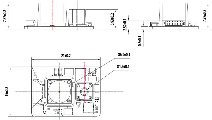
| Dimensions | TYP. 21.0 x 15 x 7.87mm³ |
| Weight | 1.35g |
| Connector | 0.8mm-6P (Model: WF08006-01207) |
NOTICE:① Accuracy is based on specific reflectivity conditions; environmental changes may affect results.② Repeatability is based on indoor and specific reflectivity conditions.③ Peak current is measured at room temperature.
1.3 Structural appearance
The overall appearance of the LiDAR is shown below:
2. Hardware Interface and Protocol
This section introduces the hardware and protocol information of the TFS20-L LiDAR.
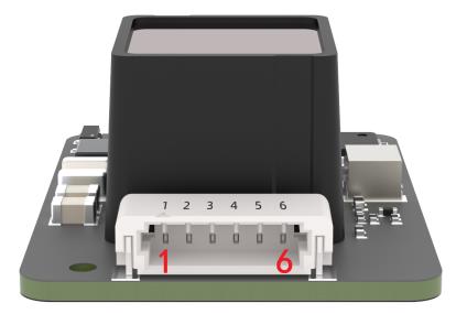
2.1 Pin sequence description
The connector terminal model is WF08006-01207, with a terminal spacing of 0.8mm.
| Pin number | Function | Explanation |
|---|---|---|
| 1 | 3V3 Laser | Laser power supply |
| 2 | 3V3GND | Ground |
| 3 | UART_TX/I2C_SDA | Transmit / Data |
| 4 | UART_RX/I2C SCL | Receive / Clock |
| 5 | GPIO | Communication chip select |
| 6 | GND | Ground |
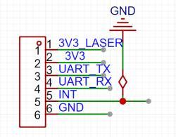
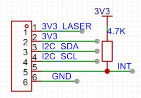
The module supports two communication modes: UART and IIC. However, only one interface can be selected for operation upon power-on.
| Mode | Configuration Requirement |
|---|---|
| UART | Connect the INT pin to ground when powering on. |
| IIC | When powered on, the INT pin needs to be pulled up with a 4.7K resistor or left floating. |
2.2 Serial data communication
| Parameter | Default | Configurability |
|---|---|---|
| Baud rate | 115200 | Configurable |
| Data bit | 8 | Non-configurable |
| Stop bit | 1 | Non-configurable |
| Parity | None | Non-configurable |
NOTICE: The baud rate can be set to 9600, 19200, 38400, 57600, 115200, 230400, 460800, 921600. The default baud rate is 115200. If an incorrect baud rate is configured, it resets to 115200.

2.3 Serial port output format
Each data packet consists of 9 bytes of hexadecimal numbers:
| Byte0-1 | Byte2 | Byte3 | Byte4 | Byte5 | Byte6 | Byte7 | Byte8 |
|---|---|---|---|---|---|---|---|
| Header | Dist_L | Dist_H | Strength_L | Strength_H | Temp_L | Temp_H | Checksum |
Data code explanation:Byte0-1: 0x59, frame header, same for each frameByte2: Dist_L distance value low 8 bitsByte3: Dist_H distance value high 8 bitsByte4: Strength_L low 8 bitsByte5: Strength_H high 8 bitsByte6: Temp low 8 bitsByte7: Temp high 8 bitsByte8: Checksum is the lower 8 bits of the cumulative sum of the first 8 bytes
3. Custom Configuration
Customers can customize parameters such as data frame format and frame rate by sending specific commands. All parameters are saved in Flash after successful configuration, so reconfiguration is not needed upon restart. All configuration commands are sent in hexadecimal (HEX).
3.1 Frame definition
| Byte0 | Byte1 | Byte2 | Byte3 ~ ByteN-2 | ByteN-1 |
|---|---|---|---|---|
| Head | Len | ID | Payload | Checksum |
Command encoding explanation:Byte0 Header: Fixed to 0x5AByte1 Len: The length of the command frame (unit: Byte)Byte2 ID: Identifies the function of each commandByte3-N-2 Data: Different meanings and lengths in different ID command framesByteN-1 Checksum: the lower 8 bits of the sum of the first N-2 bytes
3.2 Custom configuration
The table below lists general parameter configurations. Note that some commands take effect immediately, while others may require a power cycle.
| Description | Command | Response | Remarks | Default settings |
|---|---|---|---|---|
| Frame rate① | 5A 06 03 LL HH SU | 5A 04 01 5F④ | Only supports 0/20/50/100/250 Hz | 100Hz |
| Instruction trigger mode | 5A 04 04 62 | Data packet | After setting frame rate to 0, you can trigger the sensor through this command | / |
| Output format | 5A 05 05 01 655A 05 05 06 6A | 5A 05 05 01 655A 05 05 06 6A | Standard 9 bytes (cm)Standard 9 bytes (mm) | √ (cm) |
| Output control③ | On: 5A 05 07 01 67Off: 5A 05 07 00 66 | Same as command | An enable data-output command must be sent each time the power is turned on. | Enabled |
| Modify baud rate② | 5A 08 06 H1 H2 H3 H4 SU | Same as command | Example: 256000(DEC)=3E800(HEX), H1=00, H2=E8, H3=03, H4=00 | 115200 |
| Enable checksum | On: 5A 05 08 01 68Off: 5A 05 08 00 67 | Same as command | Enable / Disable | √ |
| Signal strength low threshold and output value | 5A 07 22 XX LL HH 00 | Same as command | Example: When Strength≤100, the Dist output value is changed to 1200. XX=100/10=10(DEC)=0A(HEX); 1200(DEC)=4B0(HEX) LL=B0, HH=04 | / |
CAUTION:① This command adjusts the output frequency. Default is 100Hz.② Baud rate resets to 115200 if configured incorrectly.③ Enable data-output command is required on every power-on.④ ‘SU’ stands for checksum (lower 8 bits).⑤ No save command is needed; configuration saves immediately.
4. Quick Test Guide
4.1 Tools required for test

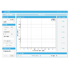
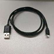
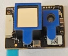
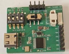
Required tools: TFS20-L, TTL-USB converter, USB cable, PC, and Test Software.
4.2 Test procedures
(1) Download the test softwareDownload the latest version from the Benewake official website. Turn off anti-virus software before decompressing to prevent file deletion. The software currently only supports Windows systems.
(2) Connection of the hardware
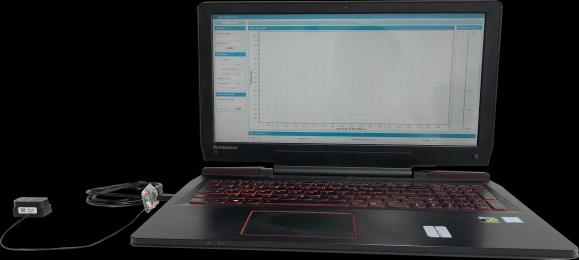
Connect “TFS20-L”, “TTL-USB board”, and “USB cable”. Ensure connections are secure. Then connect the “USB cable” to the “PC”.
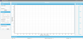
(3) Connection with softwareRun the GUI software, select “① TFmini/TFmini-S”, choose the automatically recognized communication port (e.g., “② COM9”), and select the correct baud rate (e.g., “③ 115200”). Click “CONNECT”. Upon success, the “④ TIME LINE CHART” will display the output data graph, and “⑤ REAL TIME DATA” will show real-time Distance (Dist), Effective Points, and Signal Strength.
Note:① If no data appears in “TIME LINE CHART”, check wiring. A faint red light should be visible inside the transmitting lens when powered on.② The default distance unit is cm. If changed to mm via command, the PC software may not update the unit label, but the numerical value will reflect the change (e.g., 1m becomes 1000).
5. Q&A
① No data output after connecting LiDAR to host computer.Cause-1: Poor TTL-USB board connection.Solution: Check connections between TTL-USB board, TFS20-L, and PC.Cause-2: Serial port driver not installed correctly.Solution: Re-plug USB cable and reinstall driver. Contact technical support if issues persist.
② TFS20-L heats up after working for a period.Explanation: This is normal. Slight heating of the chip and circuit board during operation is expected.
③ TFS20-L has no data output.Cause-1: V1.40C version does not output data by default on power-on.Solution: Send output enable command 5A 05 07 01 67 after powering on.Cause-2: Abnormalities due to transportation or use.Solution: Check power supply voltage. Check for faint red light in the lens. Verify wiring sequence and reliability. Ensure correct data parsing. Contact technical support if unresolved.
④ Does TFS20-L support ultra-low power mode?Answer: No. Standby power consumption is about 145 mW. Average power consumption is about 350 mW. A 10000mAh battery can last about 6 days.