Solution

LiDAR application solution for UAV position holding and hovering

Measure distance to the surface below for near-ground altitude hold, hovering, and stable-altitude cruise input.

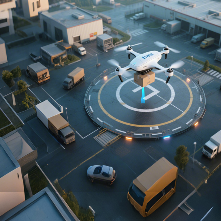
A UAV using downward-facing LiDAR for altitude hold above an industrial landing pad

Scenario

A direct reference for low-altitude vertical control

Position holding and hovering require the flight stack to manage vertical height, horizontal position, and heading. A downward LiDAR provides near-ground distance for altitude control and stable-altitude cruise but cannot establish full position hold by itself.

The engineering problem

  • Barometric and GNSS estimates do not always represent distance to the current surface below.
  • Blind zone, mounting height, and flight-stack settings must agree.
  • Maximum sensor rate or range is not the same as vehicle stability or touchdown accuracy.

Why LiDAR

A single-point ToF LiDAR provides a direct near-ground reference inside its validated range, complementing barometric, inertial, GNSS, or optical-flow inputs. Fusion, health checks, filtering, and fallback remain the flight stack’s responsibility.

How the solution works

  1. Mount downward and record orientation and sensor-to-ground mounting height.
  2. Follow the TFmini-S Manual and target documentation for power, logic level, and port setup.
  3. Verify raw range and abnormal values on real surfaces.
  4. Keep the healthy envelope inside field-validated limits.
  5. Use the input in the supported flight mode and test no-return and disconnect fallback.

Technology comparison

DimensionConditionLiDARAlternativeAlternative performanceConclusion
Near-ground height referenceCompare on the real target, mounting path, environment, control logic, and project acceptance criteria; do not compare nominal maximum range alone.Direct line-of-sight range to the surface below inside the validated envelope.Barometer / GNSSProvide different relative or global height references rather than current ground distance.

Combine ranging, positioning, fusion, and fallback for the flight mode; do not treat one range sensor as a complete altitude-hold or landing system.

公开来源公开来源 · Verified 2026-08-24

Scroll horizontally to view all columns

Installation and integration

  • Define the target, measurement axis, occlusion, wiring, and mounting space first; connect the current product manual to the target controller and record the model, interface, orientation, offset, and delivered revision.

    UAV altitude-hold solution · Target controller or host system · Target hardware and software release verified before deployment公开来源 · Verified 2026-08-24
  • Before connecting business control logic, validate healthy data, timeout handling, stop behavior, and fallback with real targets, worst-case distance, ambient light, and motion.

    UAV altitude-hold solution · Target controller or host system · Field procedure and fault handling verified on the target system公开来源 · Verified 2026-08-24

Operating limits

  • LiDAR provides distance or spatial-sensing input and does not by itself provide system positioning, safety integrity, braking, flight-stack fusion, or business outcomes; design and validate those functions separately on the target system.

    UAV altitude-hold solution公开来源 · Verified 2026-08-24

Sources

Third-party evidence

TFMini Plus used as providing UAV altitude data with a downward-pointing range sensor — CSIRO Data61

Institution
CSIRO Data61; Queensland University of Technology (QUT) Centre for Robotics
Model
—
Use
The UAV requires several sensor drivers to estimate its local position in the absence of GNSS. a TFMini Plus range sensor (Benewake, Beijing, China) pointing downwards which provid
Provenance
UAV Framework for Autonomous Onboard Navigation and People/Object Detection in Cluttered Indoor Environments 2020 DOI: 10.3390/rs12203386
Attribution
Brand-level: Benewake named in the source
Open original source ↗View evidence citation →

Sources

Verifiable specification basis

Verifiable TFmini-S reference

Supports verification of near-ground range input, interfaces, and delivery conditions. The current public material supports verification of sensor specifications and interfaces; it does not establish vehicle-level performance, system safety level, or project results.

Use the stated target, reflectivity, ambient-light, mounting, and delivered-revision conditions; revalidate in the field.

TFmini-S Datasheet

Verifiable TFS20-L reference

Supports verification of range conditions and mounting boundaries for lightweight UAVs. The current public material supports verification of sensor specifications and interfaces; it does not establish vehicle-level performance, system safety level, or project results.

Use the stated target, reflectivity, ambient-light, mounting, and delivered-revision conditions; revalidate in the field.

TFS20-L User Manual

Verifiable TFA170-L reference

Supports verification of longer-range input, power, and interface boundaries. The current public material supports verification of sensor specifications and interfaces; it does not establish vehicle-level performance, system safety level, or project results.

Use the stated target, reflectivity, ambient-light, mounting, and delivered-revision conditions; revalidate in the field.

TFA170-L Datasheet

Verifiable TF03 reference

Supports verification for outdoor mounting, interfaces, and longer-range tasks. The current public material supports verification of sensor specifications and interfaces; it does not establish vehicle-level performance, system safety level, or project results.

Use the stated target, reflectivity, ambient-light, mounting, and delivered-revision conditions; revalidate in the field.

TF03 Series Datasheet

FAQ

Frequently asked questions

Is altitude hold the same as position hold?

No. Altitude hold primarily controls vertical Z-axis height. Full position hold also controls horizontal X/Y position and heading.

Can I set the flight-controller maximum range to TFmini-S’s 12 m specification?

Do not copy it directly. The 12 m value uses a 90% reflectivity standard target. Set the healthy maximum from real surfaces, ambient light, attitude, and field tests with margin.

Resources

Resources and references

Confirm the selection with real mission conditions

Share the operating height, target surface, environment, mounting space, and flight-stack version. Our engineering team can help plan selection and validation.

Talk to an engineer

Product inquiry

Talk to a product specialist

Tell us what you need and our team will get back to you.

Product inquiry

Inquiry sent

Your inquiry has been received. We will be in touch soon.