
Technical documents
TFS20-L User Manual
This manual covers the TFS20-L LiDAR module, detailing its dToF measurement principle, technical specifications, hardware interfaces, and configuration protocols for UART and I2C c
This manual covers the TFS20-L LiDAR module, detailing its dToF measurement principle, technical specifications, hardware interfaces, and configuration protocols for UART and I2C communication.
1. Product Overview
The TFS20-L is a miniaturized single-point LiDAR module that measures distance based on direct time of flight (dToF). The laser emits a pulsed signal, which reflects off the target and is detected by a SPAD detector. Distance is calculated from the time difference.b17
1.2 Technical Specifications
| Performance Parameter | Value |
|---|---|
| Detection Range | 0.2-20m@90% reflectivity@0Klux, 0.2-15m@90% reflectivity@100Klux0.2-12m@10% reflectivity@0Klux, 0.2-9m@10% reflectivity@100Kluxb20 |
| Accuracy① | ±6cm (0.2~6m), 1% (≥6m)b20 |
| Repeatability② | 2cm (0.2~6m) @1σb20 |
| Frame rate | 0/ 20 / 50 / 100 (default) / 250Hzb20 |
| Ambient light resistance | 100KLuxb20 |
| Light source | VCSELb22 |
| Central wavelength | 905nmb22 |
| FoV | <2°b22 |
| Eye safety | Class 1 Eye-safe [EN60825]b22 |
| Average power consumption | ≤0.43Wb24 |
| Peak current③ | 130mA@3.3Vb24 |
| Power supply | DC 3.3±9%Vb24 |
| Operating temperature | -20℃ ~ +60℃b25 |
| Dimensions | TYP. 21.0 x 15 x 7.87mm³b25 |
| Weight | 1.35gb25 |
NOTICE:1. Accuracy is based on 25℃, 90% reflectivity.2. Repeatability is based on 25℃ indoors, 90% reflectivity.3. Peak current is measured at room temperature.b29
1.3 Structural Appearance
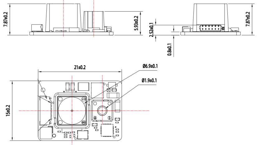
Figure 1: TFS20-L Dimensionsb32
2. Hardware Interface and Protocol
Connector model: WF08006-01207, spacing 0.8mm.b34
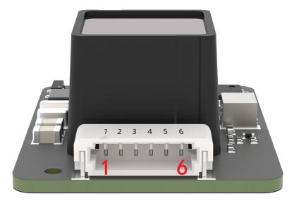
Figure 2: TFS20-L pin sequenceb36
| Pin number | Function | Explanation |
|---|---|---|
| 1 | 3V3 Laser | Laser power supply |
| 2 | 3V3GND | |
| 3 | UART_TX/I2C_SDA | Transmit / Data |
| 4 | UART_RX/I2C SCL | Receive / Clock |
| 5 | GPIO | Chip select |
| 6 | GND | Ground |
The module supports UART and IIC modes. Only one interface can be selected at power-on.b38
| Mode | Configuration |
|---|---|
| UART | Connect INT pin to ground when powering onb39 |
| IIC | INT pin pulled up with 4.7K resistor or floatingb39b42 |
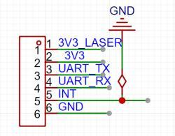
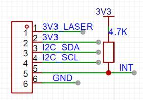
2.2 Serial Data Communication
| Parameter | Default | Configurability |
|---|---|---|
| Baud rate | 115200 | Configurable |
| Data bit | 8 | Non-configurable |
| Stop bit | 1 | Non-configurable |
| Parity | None | Non-configurable |
Baud rates supported: 9600, 19200, 38400, 57600, 115200, 230400, 460800, 921600. Default is 115200. Incorrect configuration resets to 115200.b51b52
2.3 Serial Port Output Format
Each data packet consists of 9 bytes.b53
| Byte0-1 | Byte2 | Byte3 | Byte4 | Byte5 | Byte6 | Byte7 | Byte8 |
|---|---|---|---|---|---|---|---|
| 0x59 59 | Dist_L | Dist_H | Strength_L | Strength_H | Temp_L | Temp_H | Checksum |
Byte0-1: Frame header 0x59 59Byte2-3: Distance value low/high 8 bitsByte4-5: Strength low/high 8 bitsByte6-7: Temperature low/high 8 bitsByte8: Checksum (lower 8 bits of sum of first 8 bytes)b55b56
2.4 I2C Communication
Pull up pin 5 with 4.7K resistor or leave floating for I2C mode. Pin 3 is SDA, Pin 4 is SCL.b57 Supports up to 400kps clock speed, default address 0x10.b58 Firmware V1.4.6+ supports I2C.b59 7-bit slave address range [0x08, 0x77]. Write address 0x20, Read address 0x21.b60 Wait 100ms after write before reading.b60
3. Custom Configuration
Parameters like frame format and rate can be customized via commands. Settings are saved to Flash.b65 Commands are in HEX.b65
| Byte0 | Byte1 | Byte2 | Byte3 ~ ByteN-2 | ByteN-1 |
|---|---|---|---|---|
| Head (0x5A) | Len | ID | Payload | Checksum |
Byte0: Header 0x5AByte1: LengthByte2: IDByte3-N-2: DataByteN-1: Checksumb69
3.2 Custom Configuration Examples
| Description | Command | Response | Remarks | Default settings |
|---|---|---|---|---|
| Firmware version | 5A 04 01 5F SU | 5A 07 01 V1 V2 V3 | Version V3.V2.V1 | / |
| Frame rate① | 5A 06 03 LL HH SU④ | 5A 04 01 5F | 0/20/50/100/250 Hz | 100Hz |
| Instruction trigger mode | 5A 04 04 62 | Data packet | Trigger sensor when frame rate is 0 | / |
| Output format (cm) | 5A 05 05 01 65 | 5A 05 05 01 65 | Standard 9 bytes | √ |
| Output format (mm) | 5A 05 05 06 6A | 5A 05 05 06 6A | Standard 9 bytes | / |
| Output control③ | On: 5A 05 07 01 67Off: 5A 05 07 00 66 | Same as command | Must send enable command on power-up | Enabled |
| Modify baud rate② | 5A 08 06 H1 H2 H3 H4 SU | Same as command | Example: 460800 (0x00 07 08 00) | 115200 |
| Enable checksum | On: 5A 05 08 01 68Off: 5A 05 08 00 67 | Same as command | Enable | |
| Signal strength threshold and low threshold output value | 5A 07 22 XX LL HH | Same as command | Example: Strength≤100, Dist=1200 | / |
CAUTION:1. Default frame rate 100Hz. Supports 0, 20, 50, 100, 250Hz.2. Wrong baud rate resets to 115200.3. Enable data-output command required on each power-up.4. ‘SU’ is checksum.5. Configuration commands save immediately.b76b77b85b86
4. Quick Test Guide
4.1 Tools Required
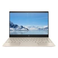
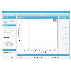
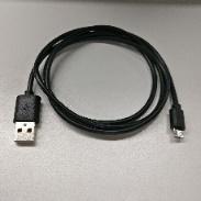
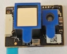
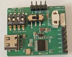
TFS20-L, TTL-USB converter, USB cable, PC, Test Softwareb104
4.2 Test Procedures
(1) Download test software from Benewake website. Disable antivirus during extraction. Windows only.b106
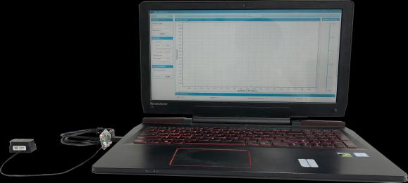
(2) Hardware Connection: Connect TFS20-L to TTL-USB board and PC via USB.b110
Figure 3: LiDAR and PC interfacingb109
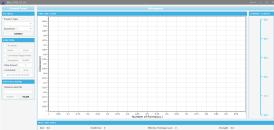
(3) Software Connection: Run GUI, select “TFmini/TFmini-S”, choose COM port and baud rate (115200), click “CONNECT”. View data in “TIME LINE CHART” and “REAL TIME DATA”.b115
Figure 4: GUI software and LiDAR interfacingb114
Note:1. Check wiring if no data. Faint red light visible when powered.2. Distance unit defaults to cm. If changed to mm, software chart still shows cm unit but values change.b116b117
5. Q&A
1. No data output: Check TTL-USB connection and drivers.b121
2. Heating: Normal operation.b122
3. No data output: V1.4.0 requires enable command (5A 05 07 01 67). Check power and wiring.b123
4. Ultra-low power mode: Not supported. Standby ~145 mW, Average ~430 mW.b124
Appendix: I2C REGISTER TABLE
| Address | R/W | Name | Description | Initial Value |
|---|---|---|---|---|
| 0x00 | R | DIST_LOW | Distance low byte (cm) | - |
| 0x01 | R | DIST_HIGH | Distance high byte | - |
| 0x02 | R | AMP_LOW | Amplitude low byte | - |
| 0x03 | R | AMP_HIGH | Amplitude high byte | - |
| 0x04 | R | TEMP_LOW | Temperature low byte (0.01 Celsius) | - |
| 0x05 | R | TEMP_HIGH | Temperature high byte | - |
| 0x06 | R | TICK_LOW | Timestamp low byte | - |
| 0x07 | R | TICK_HIGH | Timestamp high byte | - |
| 0x08-0x09 | R | ERROR_LOW | Error code | Hold |
| 0x0A | R | VERSION_REVISION | Revised version | - |
| 0x0B | R | VERSION_MINOR | Minor version | - |
| 0x0C | R | VERSION_MAJOR | Major version | - |
| 0x10-0x1D | R | SN | Serial Number (14 bytes ASCII) | - |
| 0x20 | W | SAVE | Write 0x01 to save settings | - |
| 0x21 | W | SHUTDOWN/REBOOT | Write 0x02 to reboot | - |
| 0x22 | W/R | SLAVE_ADDR | Slave Address [0x08, 0x77] | 0x10 |
| 0x23 | W/R | MODE | 0x00: Continuous; 0x01: Trigger | 0x00 |
| 0x24 | W | TRIG_ONE_SHOT | Trigger once (trigger mode only) | - |
| 0x25 | W/R | ENABLE | 0x00: Off; 0x01: On | 0x01 |
| 0x26 | W/R | FPS_LOW | Frame rate low byte | 0x64 |
| 0x27 | W/R | FPS_HIGH | Frame rate high byte | 0x00 |
| 0x29 | W | RESTORE_FACTORY_DEFAULTS | Write 0x01 to restore defaults | - |
| 0x2A | W/R | AMP_THR_LOW | Amplitude threshold low | 0x2C |
| 0x2B | W/R | AMP_THR_HIGH | Amplitude threshold high | 0x01 |
| 0x2C | W/R | DUMMY_DIST_LOW | Dummy distance low | 0xFF |
| 0x2D | W/R | DUMMY_DIST_HIGH | Dummy distance high | 0xFF |
| 0x2E | W/R | MIN_DIST_LOW | Min distance low (mm) | 0x00 |
| 0x2F | W/R | MIN_DIST_HIGH | Min distance high (mm) | 0x00 |
| 0x30 | W/R | MAX_DIST_LOW | Max distance low (mm) | 0xFF |
| 0x31 | W/R | MAX_DIST_HIGH | Max distance high (mm) | 0xFF |
| 0x3A-0x3F | R | SIGNATURE | ‘TFS20-L’ | - |