
Technical documents
TF350 RS-485 / RS-232 User Manual
TF350 RS-485 / RS-232

TF350 RS-485 / RS-232
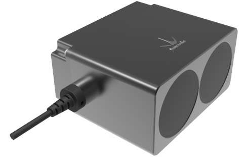
Benewake (Beijing) Co., Ltd

PREFACE
Dear users: Thank you for choosing Benewake products. For the purpose of offering better operation experience to you, we hereby write this manual for an easier and simpler operation of our product, hoping to better solve the common problems you may meet. This user manual contains the relevant information on product introduction, usage and maintenance of TF350 RS-485 / RS-232, covers the product operation introduction and common problem solutions. Please read this manual carefully before using the product. Remember the precautions to avoid hazards, and please follow the described steps in the manual when using it.
If you have any problems in the process of usage, you are welcome to contact Benewake at any time for help.
Contact Details Official website: https://ai.benewake.com/en/products/tf350/ TEL:+86-10-57456983 Technical questions,please contact: support@benewake.com Consult sale information or request brochure,please contact: bw@benewake.com
Headquarters Address Benewake (Beijing) Co., Ltd. 3rd Floor, Haiguo Jiaye Sci-Tech Park, Haidian District, Beijing, China
Copyright Statement This User Manual is copyright © of Benewake. Please do not modify, delete or translate the description of this manual contents without the official written permission from Benewake.
Disclaimer As our products are constantly improving and updating, the specifications of TF350 RS-485 / RS-232 are subject to change. Please refer to the official website for latest version.
CONTENTS
1 OVERVIEW ........................................................................................................................ 1 1.1 Failure scenarios .......................................................................................................1 1.2 Symbols and document conventions ......................................................................... 2 2 PRODUCT DESCRIPTION .....................................................................................................3 2.1 Appearance Overview ...............................................................................................3 2.2 Dimensional drawing ................................................................................................3 2.3 Measuring principle .................................................................................................. 4 2.4 Technical specification .............................................................................................. 4 2.5 FoV ...........................................................................................................................6 3 ELECTRICAL INSTALLATION ................................................................................................7 3.1 Pin and wire color assignment .................................................................................. 7 3.2 Connector ................................................................................................................. 8 3.3 Wire cross-sections ................................................................................................... 8 3.4 General conditions for data interface ........................................................................ 9 3.5 Wiring the RS-232 Interface .......................................................................................9 3.6 Wiring the RS-485 Interface ..................................................................................... 10 4 COMMUNICATION PROTOCOLS ........................................................................................ 11 4.1 Communication protocol ......................................................................................... 11 4.2 Data frame ..............................................................................................................11 4.3 Modbus .................................................................................................................. 12
4.3.1 Protocol description ........................................................................................ 12 4.3.2 Function code ................................................................................................. 12 4.3.3 Accessible register address ............................................................................. 13 4.3.4 Common commands for Modbus ..................................................................... 14
5 CUSTOM CONFIGURATION ............................................................................................... 16 5.1 Command protocol ................................................................................................. 16 5.2 Common commands ............................................................................................... 16 5.3 Command editing ................................................................................................... 18 6 OPTIONAL ACCESSORIES ................................................................................................. 19 6.1 Self-cleaning module .............................................................................................. 19 7 QUICK START GUIDE ........................................................................................................ 20 7.1 Connection and basic test ........................................................................................20 7.2 Troubleshooting guide for initial test ....................................................................... 21 7.3 Working mode ........................................................................................................ 22 7.4 Influences of object surfaces on the measurement ...................................................22 8 TROUBLESHOOTING ........................................................................................................ 26 Attachment 1:Reflectivity of Different Materials ................................................................... 28
OVERVIEW
1 OVERVIEW
The Reference Manual is a complement to the Operating Instructions for TF350. The Operating Instructions for TF350 describes how to set up and configure the interfaces. The Reference Manual contains detailed information about the interfaces including syntax and available functionality. It focuses on TF350 specific topics and does not describe the basic technology behind each interface. The details of the result output formatting and the contents and syntax of the command channels are shared by several interfaces. They are described in an appendix valid for all relevant interfaces.
1.1 Failure scenarios
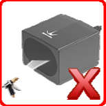
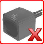
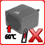
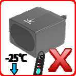
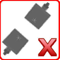
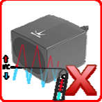
As a precision optical distance sensor, TF350 ’ s performance is greatly affected by environment. Certain scenarios will even damage TF350. Each of these failure scenarios have been tested in real field tests. Table 1 Failure scenarios of TF350
| Parameter | Value |
|---|---|
| Scenario | Description Scenario Description |
| Do not cover the laser | Avoid moving objects in |
| window. | the detection field. |
| Avoid the presence of | Avoid condensation. |
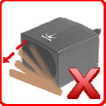
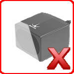
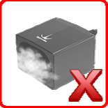
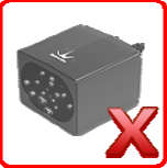
heavy smoke, fog and rain in the detection field. Avoid direct exposure to Avoid exposure to high pressure cleaning. strong light source with
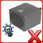
same wavelength.
OVERVIEW
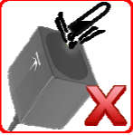
| Parameter | Value |
|---|---|
| Do not exposure to | Avoid extreme |
| corrosive liquids. | vibrations. |
| Do not use in extremely | Do not use in extremely |
| low temperature | high temperature |
| environments. | environments. |
| Avoid exposure to | Avoid direct exposure |
| sudden and extreme | to another LiDAR with |
| temperature changes. | same wavelength. |
1.2 Symbols and document conventions
The following symbols and conventions are used in this document:
WARNING Indicates a situation presenting possible danger, which may lead to death or serious injuries if not prevented.
CAUTION Indicates a situation presenting possible danger, which may lead to moderate or minor injuries if not prevented.
NOTICE Indicates a situation presenting possible danger, which may lead to property damage if not prevented.
NOTE Indicates useful tips and recommendations.
PRODUCT DESCRIPTION
2 PRODUCT DESCRIPTION
2.1 Appearance Overview
①
②
③
④
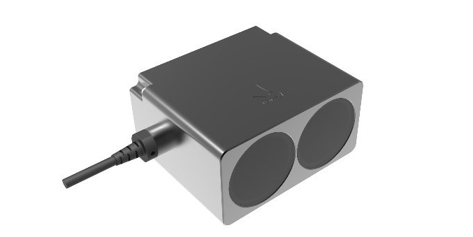
Figure 1 Module view of TF350
1 Cable with male connector, Molex SD-51021-007, 7pin also called MH1.25-7P-W/B 2 Laser window (Receiving) 3 Laser window (Emitting) 4 3mm diameter hole (6mm deep) for mounting (6x) 2.2 Dimensional drawing
①
② ③
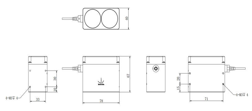
Figure 2 Dimensional drawing of TF350 (① Front;② Top; ③ Bottom; Unit: mm)
PRODUCT DESCRIPTION
2.3 Measuring principle
TF350 is a typical Pulse Time of Flight (PToF) sensor. It adopts an incoherent energy receiving mode, and the measurement is mainly based on Pulse counting. TF350 emits a narrow pulse laser, which is collimated by the transmitting lens, which enters the receiving system after being reflected by the measured target and is focused on the APD detector by the receiving lens. The time between the transmitted signal and the received signal is calculated through the circuit amplification and filtering, and the distance between TF350 and the measured target can be calculated through the speed of light.
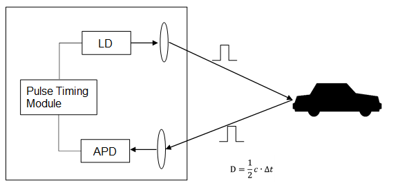
Figure 3 Pulsed time of flight (PToF)
2.4 Technical specification
Table 2 Data sheet of TF350
| Parameter | Value |
|---|---|
| Parameters | Minimum Typical Maximum |
| Range (@90% reflectivity, 0klux) | 0.2m 350m |
| Range (@10% reflectivity, 0klux) | 0.2m 110m |
| Range (@90% reflectivity, 100klux) | 0.2m 300m |
| Performance Range (@10% reflectivity, 100klux) | 0.2m 100m |
| Accuracy | ±10cm (<10m), 1% (≥10m) |
| Distance resolution | 1cm |
| Frame rate | 1Hz 100Hz 1000Hz |
| Repeatability | 1σ: <3cm |
| Parameters | Minimum Typical Maximum |
| Optical Light source | LD |
| parameters Central wavelength | 905nm |
PRODUCT DESCRIPTION
| Parameter | Value |
|---|---|
| Photobiological safety | Class1(EN60825) |
| FoV | 0.35° |
| Ambient light immunity | 100Klux |
| Environment Operation temperature | -25℃ 60℃ |
| Enclosure rating | IP67 |
| Supply voltage | 5V DC 24V DC |
| Average current | ≤150mA @ 5V, ≤80mA @ 12V, ≤ |
50mA @ 24V
| Parameter | Value |
|---|---|
| Power consumption | ≤1W |
| Connections Overvoltage protection | 300V |
| Polarity protection | 200V |
| Communication interface level | LVTTL |
(3.3V)
| Parameter | Value |
|---|---|
| Communication interface | RS-485 / RS-232 |
| Dimension | 78mm*67mm*40mm(L*W*H) |
| Housing | Aluminum alloy |
| Others Optical window | Infrared optical glass (HWB760) |
| Storage temperature | -40℃ 85℃ |
| Weight | 222g ± 3g |
| Cable length | 70cm |
NOTICE Only the frame rate satisfying the following formula is supported.
Frame rate = a × 10 b, a ∈ {1,2,3,4,5,6,7,8,9}, b ∈ {0,1,2,3}
If a value which does not satisfy this formula is set, TF350 will set its frame rate to 100Hz. The normal frame rate is under 1kHz, but its maximum frame rate can reach as much as 7kHz. Please contact us if you need upper frame rate. The basic technical specifications, like accuracy and repeatability, are measured with white background board (90% reflectivity) at 0klux condition.
PRODUCT DESCRIPTION
2.5 FoV
The field-of-view, FoV, is the angle covered by the LiDAR sensor. The horizontal FoV of TF350 is about 0.35° and the vertical FoV of TF350 is approx. 0.1°.
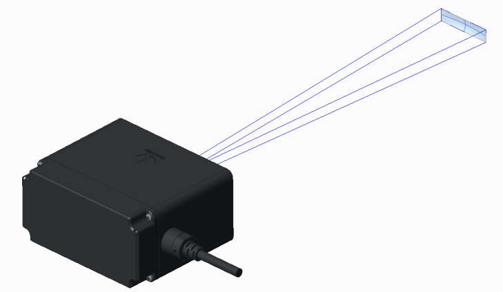
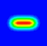
Figure 4 FoV of TF350. Horizontal divergence 0.35°, vertical divergence 0.1°
NOTICE
0.35° and 0.15° are theoretic values. Because the manufacturing error and the installing error exist, there is divergence between each TF350 ’ s actual FoV and its theoretic values.
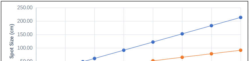
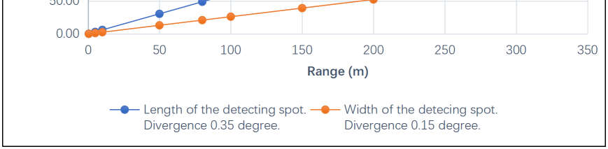
Figure 5 Spot size of TF350 at different ranges
COMMUNICATION PROTOCOLS
3 ELECTRICAL INSTALLATION
3.1 Pin and wire color assignment
TF350 ’ s cable has six 26 AWG wires. The connector is Molex SD-51021-007 1.25 W/B-7Pin (MH1.25-7P-W/B).
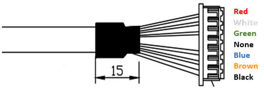
Figure 6 Male connector, Molex SD-51021-007 1.25 W/B-7Pin
Table 3 Pin assignment on 7-pin male connector Pin Signal Color Function 1 VCC Red DC 5-24V 2 RS-485-B/RS-232-RXD White RS-485-B/RS-232 Receive 3 RS-485-A/RS-232-TXD Green RS-485-A/RS-232 Transmit 4 N/A N/A N/A 5 UART_RXD Blue UART receive (Debug) 6 UART_TXD Brown UART Transmit (Debug) 7 GND Black Ground
Notice
The UART interface of TF350 RS-485/RS-232, PIN 5 and PIN 6, is a debug interface. Please do not use it.
COMMUNICATION PROTOCOLS
3.2 Connector
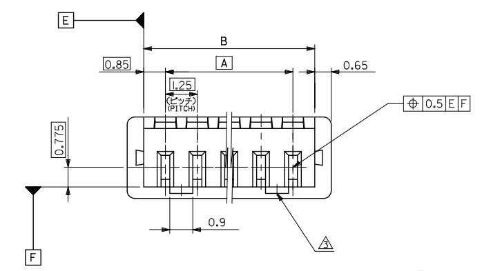
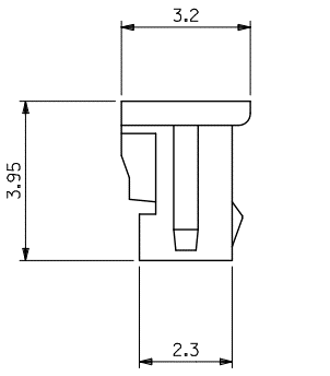
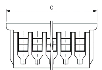
A: 7.5mm, B: 9.2mm, C: 10.5mm
Figure 7 Dimension drawing of connector: Molex SD-51021-007 1.25 W/B-7Pin
3.3 Wire cross-sections
CAUTION If you use flexible connecting cables with stranded wire, then you must not use ferrules when connecting the wires to the terminals on TF350. Wire all connections with copper cables!
Use the following wire cross-sections: supply voltage at least 0.13 mm ² (approx. 26 AWG), if local power supply in the immediate vicinity. supply voltage at least 0.21 mm ² (approx. 24 AWG) at maximum length of 2m (6.562 ft), if the connection is made to an existing 24 V DC supply. switching outputs minimum 0.13 mm² (approx. 26 AWG), maximum cable length 2m (6.562 ft) with 0.21 mm² (approx. 24AWG). data interface minimum 0.13mm² (approx. 26AWG). Lay all cables such that there is no risk of tripping and all cables are protected against damage. On the usage of a typical power supply with a nominal voltage of 24V DC ±5%, the following maximum cable lengths are allowed for the supply of the operating voltage:
COMMUNICATION PROTOCOLS
Table 4 Maximum cable lengths for the supply voltage
| Parameter | Value |
|---|---|
| Wire cross-section | Cable length |
| 0.13 mm2 (approx. 26AWG) | 4 m (13.1 ft) |
| 0.32 mm2 (approx. 22AWG) | 10 m (32.81 ft) |
| 0.81 mm2 (approx. 18AWG) | 20 m (65.62 ft) |
3.4 General conditions for data interface
The table below shows the recommended maximum length of cable as a function of the data transmission rate selected. Table 5 Maximum cable lengths for the data interfaces
| Parameter | Value |
|---|---|
| Interface type | Transmission rate Maximum cable length |
| RS232 | 115200 bps 10 m (32.81ft) |
| RS485 | 115200 bps 10 m (32.81ft) |
NOTICE With appropriate cable termination, termination in accordance with related specification. Use screened cable(twisted-pair) with at least 26 AWG.
3.5 Wiring the RS-232 Interface Pay attention to max. cable length as per section 3.4 “General conditions for the data interface”.
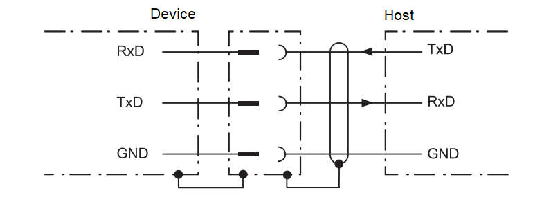
Figure 8 Wiring of the RS-232 interface
COMMUNICATION PROTOCOLS
3.6 Wiring the RS-485 Interface
Pay attention to max. cable length as per section 3.4 “General conditions for the data interface”.
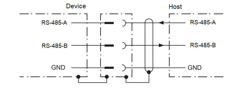
Figure 9 Wiring of the RS-485 interface
COMMUNICATION PROTOCOLS
4 Communication Protocols
The industrial version of TF350 supports two communication interfaces, RS-232 and RS-485. The default interface is RS-485. These two interfaces cannot work simultaneously. The communication interface can be switched by certain command.
NOTICE The RS-485 interface in industrial TF350 is a debug interface. Please do not use it.
4.1 Communication protocol
Table 6 Communication protocol of the RS-232 protocol
| Parameter | Value |
|---|---|
| Character | Value Configurability |
| Baud rate | 115200 Configurable |
| Data bit | 8 Non-configurable |
| Stop bit | 1 Non-configurable |
| Parity | None Non-configurable |
4.2 Data frame
A standard data frame consists of 9 bytes of hexadecimal numbers, which contains distance and signal strength.
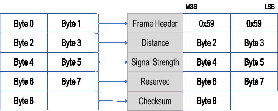
Figure 10 Data communication: User protocol frame format of RS-485
COMMUNICATION PROTOCOLS
4.3 Modbus
The RS-485 interface of TF350 supports Modbus protocol.
NOTICE The TF350 RS485 interface is in half-duplex mode. Based on reliability considerations, it is not recommended to use a baud rate above 115200 for communication.
4.3.1 Protocol description The communication protocol format of Modbus is different from it of the RS-232 and RS-485 interface. Check the following tables for detailed protocols. Table 7 Command format of Modbus Header Function code Register Addr. Register value CRC_low CRC_high
01 (Default) 03 00 00 00 01 xx xx Table 8 Data frame format of Modbus Header Function code Length Frame Dist_high Dist_low CRC_low CRC_high
01 (Default) 03 02 xx xx xx xx
NOTICE
All the data mentioned in the protocol are in hexadecimal.
4.3.2 Function code The Modbus of TF350 only supports the basic function of reading and writing register. The function codes are listed in the following table. Table 9 List of function codes of Modbus
Function code Description 03 Read register 06 Write register
COMMUNICATION PROTOCOLS
4.3.3 Accessible register address Table 10 List of accessible register address of function code (0x03) Register Addr. Definition Description
00 00 Dist Distance value 00 01 Strength Signal strength. Not currently supported.
00 03 Upper 16 bits of time stamp Upper 2 bytes of time stamp. Unit: ms
00 04 Lower 16 bits of time stamp Lower 2 bytes of time stamp. Unit: ms
00 06 firmware version Upper 16 bits of 0x00 and main version number
00 07 firmware version Lower 16 bits of Sub-version and revised version number
Table 11 List of accessible register address of function code (0x06) Register Addr. Definition Description
00 80 Save settings Perform ‘Save’ operation with any data being written to the register.
00 81 Shut down / Reboot 0x00: Shut down
0x01: Reboot
00 82 Disable Modbus 0x01: Disable Modbus 00 83 Upper 16 bits of baud rate Save and reboot to take effect.
00 84 Lower 16 bits of baud rate Save and reboot to take effect.
00 85 Slave ID Save and reboot to take effect. 00 86 fps Save and reboot to take effect. 00 87 Working mode Save and reboot to take effect.
0x00: Continuous working mode
0x01: Command-trigger mode
00 89 Restore default Perform ‘Restore default’ operation with any data being written to the register.
Save and reboot to take effect.
COMMUNICATION PROTOCOLS
4.3.4 Common commands for Modbus The default interface of industrial TF350 is general RS-485 protocol. Send commands listed in Table 12 Command used to enable Modbus protocol in RS-485 interface to enable Modbus protocol. Table 12 Command used to enable Modbus protocol in RS-485 interface
| Parameter | Value |
|---|---|
| Function | Command Response Description |
| Enable Modbus | 5A 05 6F 00 CE Same as command Save and reboot to take effect |
| Set Modbus Address | 5A 05 70 ADDR SU 5A 05 70 00 CF / |
WARNING TF350 only supports RTU mode to communicate in serial link. The default address of Modbus is 0x01. The commands listed in the following table are based on default address. If the address is changed, the commands need to make corresponding changes. See 4.3.1 for detailed information. The commands listed in the following table will only take effect under Modbus protocol. Do not send the command that is not in the list below.
Table 13 List of common commands of Modbus Function Command Response Description
Data frame: DH: Upper 8 bits of distance
Obtain distance 01 03 00 00 00 01 03 02 DH DL: Lower 8 bits of distance
01 84 0A DL CL CH CH: Upper 8 bits of CRC
CL: Lower 8 bits of CRC DH: Upper 8 bits of distance DL: Lower 8 bits of distance
| Parameter | Value |
|---|---|
| Obtain distance | 01 03 04 DH SH: Upper 8 bits of signal strength |
| and signal | 01 03 00 00 00 02 C4 0B DL SH SL CL |
| strength | CH SL: Lower 8 bits of signal strength |
CH: Upper 8 bits of CRC CL: Lower 8 bits of CRC
COMMUNICATION PROTOCOLS
Obtain firmware 01 03 00 06 00 01 03 04 00 VM: Main version number version 02 24 0A VM VS VC CL CH VS: Sub-version number
VC: Revised version number
01 06 00 83 Set baud rate to 9600
01 06 00 83 BH1 BH2 CL CH BH1 BH2 CL (0x00002580):
Set baud rate 01 06 00 84 BL1 CH BH1=00 BH2=00 CL=78 CH=22,
BL2 CL CH BL1 BL2 CL CH 01 06 00 84 BL1=25 BL2=80 CL=D2
CH=D3 IH: Upper byte of ID
Change Slave ID 01 06 00 85 IH IL 01 06 00 85 IH IL: Lower byte of ID
CL CH IL CL CH Change slave ID to 0x0002:
IH=00 IL=02 CL=19 CH=E2
01 06 00 86 FH 01 06 00 86 Set frame rate to 100Hz (0x0064):
Set frame rate FL CL CH FH FL CL CH
FH=00 FL=64 CL=69 CH=C8
Save setting 01 06 00 80 00 00 88 22 01 06 00 80 00 00 88 22 Save and restart to take effect
Disable Modbus 01 06 00 82 00 01 E8 22 01 06 00 82 00 01 E8 22 Save and restart to take effect
CUSTOM CONFIGURATION
5 CUSTOM CONFIGURATION
5.1 Command protocol
To meet the need of different customers, TF03 released several configuration parameters. These parameters, such as data format, frame rate, could be modified by certain command. All the parameters will be stored in flash after configured successfully and customers don’t need to configure again when restart. Table 14 Description of TF03 command protocol
| Parameter | Value |
|---|---|
| Byte | Definition Description |
| Byte 0 | Header Fixed to 0x5A |
| Byte 1 | Len The length of the command frame (unit: Byte) |
| Byte 2 | ID Identifies the function of each command |
| Byte 3~Byte N-2 | Payload Different meanings and lengths in different ID |
command frames
Byte N-1 Check sum the lower 8 bits of the sum of the first N-2 bytes
5.2 Common commands
Table 15 List of TF03’s common commands
| Parameter | Value |
|---|---|
| Description | Command Response Remark Default setting |
| Obtain firmware | 5A 04 01 5F 5A 07 01 VA VB The version number / |
| version | VC SU VC.B.A |
| System reset | 5A 04 02 60 5A 05 02 00 61 / / |
LL: lower 8
Modify frame rate 5A 06 03 LL HH SU command Same as bits 100Hz
HH: higher 8 bits
On: 5A 05 07 01 Same as
Output control 67 command / Enabled
Off: 5A 05 07 00
CUSTOM CONFIGURATION
| Parameter | Value |
|---|---|
| command Enable | 5A 05 07 00 66 Same as / Disabled |
| triggering mode | command |
| Trigger | Only works in command |
| measurement | 5A 04 04 62 Data frame triggering / |
mode
| Parameter | Value |
|---|---|
| Change baud | 5A 08 06 H1 H2 Same as Command See 5.3 115200 |
| rate | H3 H4 SU command editing |
| Restore default settings | 5A 04 10 6E 5A 05 10 00 6F / / |
| Save settings | 5A 04 11 6F 5A 05 11 00 70 / / |
Unit: cm
Over range 5A 06 4F LL HH LL: lower 8 threshold setting SU 5A 05 4F 00 AE bits 35000
HH: higher 8 bits
| Parameter | Value |
|---|---|
| Switch | RS-485: 5A 05 |
| communication | 45 01 A5 5A 05 45 00 A4 / RS-485 |
| interface | RS-232: 5A 05 45 02 A6 |
| Modify RS-232 | 5A 08 50 H1 H2 5A 05 50 00 AF ID = (H4<<24) +(H3<<16) 0x03 |
| arbitration ID | H3 H4 SU +(H2<< 8) +H1 |
| Modify RS-232 | 5A 08 51 H1 H2 5A 05 51 00 B0 ID=(H4<<24) +(H3<<16) 0x3003 |
H3 H4 SU +(H2<< 8) +H1
Modify baud 5A 08 52 H1 H2 rate=(H4<<24) Baud rate of RS-232 H3 H4 SU 5A 05 52 00 B1 +(H3<<16) 1Mbits/s
+(H2<<8) +H1
WARNING Do not send the command that is not in the list above.
CUSTOM CONFIGURATION
NOTE Baud rate of RS-485 can be set to 9600, 14400, 19200, 38400, 56000, 57600, 115200, 128000, 230400, 256000, 460800, 512000, 750000, and
921600. If other value were set, TF03 will set it to 115200.
5.3 Command editing
This section describes the Command Channel of TF03 which is used to read and set TF03’s working parameters. The command channel is available via all the interfaces. A standard TF03 command consists of frame header, command length, command ID, parameters and checksum. Follow these steps to generate a command: Choose the right command ID and confirm its length Convert parameter from the decimal value to hexadecimal value Fill the hexadecimal parameter into the command Calculate the checksum and fill its low 8-bits into the command For example, changing the baud rate to 460800. Firstly, choose the ID of changing frame rate, which is 0x06. Secondly, change 460800 (decimal number) to hexadecimal
| Parameter | Value |
|---|---|
| number, which is 0x00 07 08 00. Thirdly, fill the parameter into the command, like | 5A |
| 08 06 00 08 07 00 SUM. | Finally calculate the sum of the first 7bytes and take its low |
| 8bits, we will have the complete command, | 5A 08 06 00 08 07 00 77. |
| Header | Length ID Hexadecimal parameters Checksum |
Fixed: 0x5A Length of the command (Number of bytes) ID of the command Hexadecimal parameters Little-endian mode Lower 8 bits of the sum of previous bytes
Figure 11 Command syntax of TF03
OPTIONAL ACCESSORIES
6 OPTIONAL ACCESSORIES
NOTE The following accessories are not standard accessories, please contact relevant sales or technical personnel if necessary.
6.1 Extension cord For testing purposes, we prepared an extension Dupont cord. See Figure 12 Extension cord for test for detailed information.
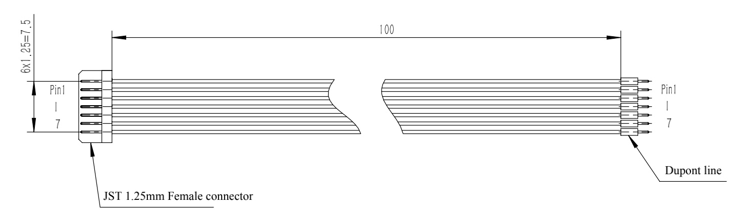
Figure 12 Extension cord for test
NOTE This extension cord is free, but it ’ s not a standard accessory. Please contact us if needed.
NOTE The following accessories are not standard accessories, please contact relevant sales or technical personnel if necessary.
QUICK START GUIDE
7 QUICK START GUIDE
7.1 Connection and basic test
NOTE The product package contains only TF350 and factory certificate. If you need USB converter, please contact our sales or technical support.
Download the latest version BW_TFDS from https://ai.benewake.com/en/contact/#inquiry onto your PC or laptop.
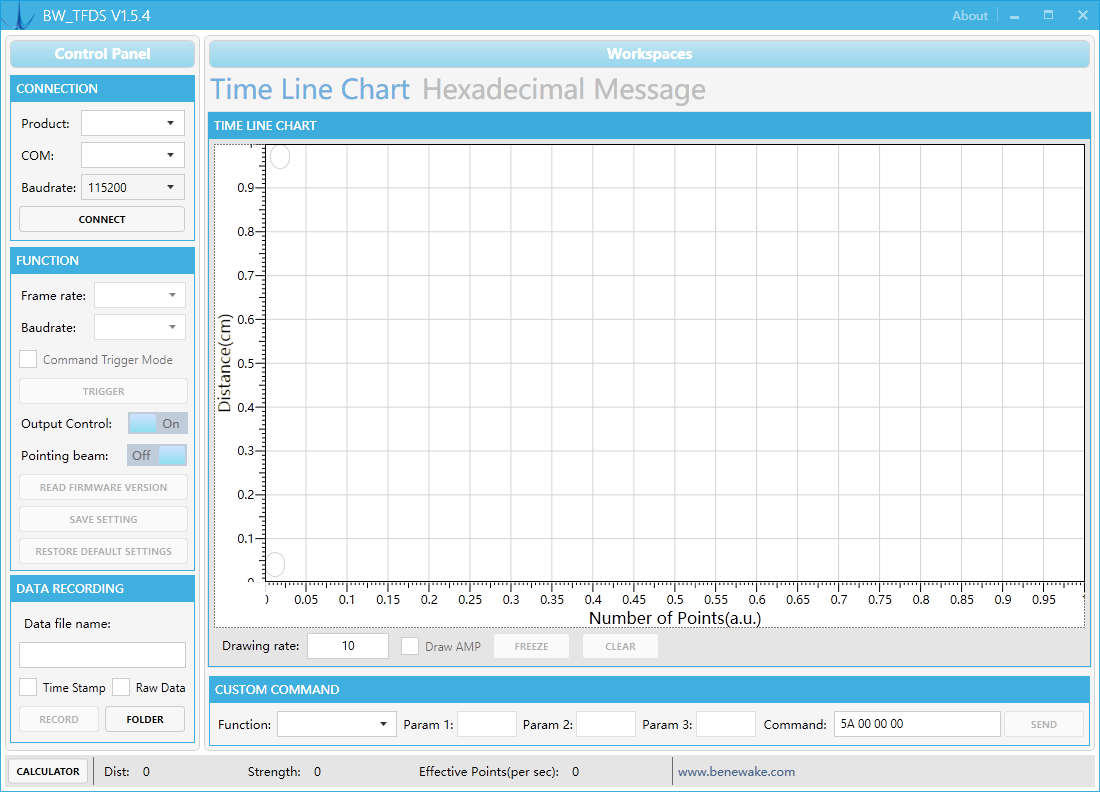
Figure 13 Benewake testing GUI for TF series
See Figure 13 Benewake testing GUI for TF series of the GUI. Connect TF350 to the PC or laptop with a paired USB converter cable as shown in Figure 14 TF350 connecting to PC. The RS-485 version TF350 needs a RS-485-USB converter, and the RS-232 version TF350 needs a RS-232-USB converter.
QUICK START GUIDE

Interface
converter
Figure 14 TF350 connecting to PC
Run BW_TFDS.exe, choose the right baud rate and communication port, and click CONNECT to start the test.
7.2 Troubleshooting guide for initial test
In the default working mode, TF350 will automatically output data when connected to the PC following 7.1Connection and basic test. If you cannot read data from GUI properly, follow these steps to locate and solve problems. S1. Check if there is red light inside TF350 through its window.
No. Check power supply. If the power supply is normal, please contact Benewake service. Yes. Proceed to S2. S2. Check whether the USB converter is paired with TF350. For example,
TF350-100 RS-232 needs a USB-RS-232 converter. No. Change a paired USB converter then try again. Yes. Proceed to S3. S3. Check signal wiring. See section 3.1 Pin and wire color assignment for
detailed wiring information. Incorrect. Fix wiring. Correct. Proceed to S4. S4. Some USB converters can generate more than one COM port. Try to connect
through different COM port.
QUICK START GUIDE
If all the COM ports don’t have data output, proceed to S5. S5. Send the command of reading firmware version, 5A 04 01 5F, through
every COM ports. Try to read response. If all the COM ports have no response, please contact Benewake service. If one of the COM ports has correct response, send the command of restore default, 5A 04 10 6E, through this COM port. After sending this command, if the TF350 still doesn ’ t work, please contact Benewake service.
7.3 Working mode
TF350 has three different working modes. Automatic output mode. This is the default working mode. The default frame rate of this mode is 10Hz. Command triggering mode. In this mode, TF350 will not output data automatically. TF350 output measuring data only when it receives the triggering command. Low power consumption mode. In this mode, TF350 still output measuring data automatically. But the maximum frame rate has been restricted to 5Hz. Meanwhile its power consumption is reduced to 350mW.
NOTE Only the RS-485 interface supports low power consumption mode.
7.4 Influences of object surfaces on the
measurement
The signal received from a perfectly diffuse reflecting white surface corresponds to the definition of a remission of 100%. As a result of this definition, the remissions for surfaces that reflect the light bundled (mirrored surfaces, reflectors), are more than 100%.
QUICK START GUIDE

Figure 15 Reflection of the laser beam at the surface of an object
The majority of surfaces reflect the laser beam diffusely in all directions. The reflection of the laser beam will vary as a function of the surface structure and color. Light surfaces reflect the laser beam better than dark surfaces and can be detected by the TF350 over larger distances. Brilliant white plaster reflects approx. 100% of the incident light, black foam rubber approx. 2.4%. On very rough surfaces, part of the energy is lost due to shading. The detecting range of the TF350 will be reduced as a result.
Figure 16 Reflection angle
The reflection angle is the same as the angle of incidence. If the laser beam is incident perpendicularly on a surface, the energy is optimally reflected (Figure 16 Reflection angle). If the beam is incident at an angle, a corresponding energy and detecting range loss is incurred.
QUICK START GUIDE

Figure 17 Degree of reflection
If the reflected energy returned is over 100% (basis: Kodak standard) the incident beam is not reflected diffusely in all directions, but is reflected in a specific direction. As a result, a large portion of the energy emitted can be received by the laser distance measurement device. Plastic reflectors (“cats’ eyes”), reflective tape and triple prisms have these properties.

α
α
Figure 18 Mirror surfaces
At mirror surfaces the laser beam is almost entirely deflected (Figure 18 Mirror surfaces). Instead of the surface of the mirror, it is possible that the object on which the deflected laser beam is incident may be detected.
QUICK START GUIDE
Figure 19 Object smaller than diameter of the laser beam
Objects that are smaller than the diameter of the laser beam cannot reflect all the energy of the laser light (Figure 19 Object smaller than diameter of the laser beam). The energy in the portion of the laser light that is not reflected is lost. This means that the detecting range is less than would be possible theoretically based on the surface of the object.
= ℎ (1, 2)
Figure 20 Staircase object
Staircase objects have two or more planes (Figure 20 Staircase object). The energy in the portion of the laser light that is reflected by different plane is different. TF350 will calculate a weighted averaging energy. The measured value will possible theoretically be the weighted average of distances from TF350 to different platform.
TROUBLESHOOTING
8 TROUBLESHOOTING
NOTICE
Claims under the warranty rendered void! The housing screws of the TF350 are sealed. Claims under the warranty against Benewake will be rendered void if the seals are damaged or the device opened. The housing is only allowed to be opened by authorized service personnel.
This chapter describes how to identify and rectify errors and malfunctions during the operation of TF350. Table 17 Troubleshooting and rectification
Fault Possible cause Solution
Optical signal was Remove the obstacle or
Measurement exceeds blocked. adjust the detecting the allowed error. direction.
The target is a low Paste a reflector on target reflectivity object. object. Protective film has Remove the protective film. not been removed.
| Parameter | Value |
|---|---|
| Measurements in the | Carefully clean optics using |
| near range with no | Contaminated or soft, fluff-free cloth. |
| measurement target. | scratched window. If the optics are scratched, |
contact Benewake service.
Rain or fog Enable rain-fog filter
| Parameter | Value |
|---|---|
| TF350 is not | Wiring fault in the Check wiring. |
| transmitting a | data connection. |
| measured result. | Wrong USB converter. Check USB converter. |
Check baud rate of the
Data transmitted is Baud rate mismatch. receiving device. garbage. Check TF350’s baud rate
setting.
A certain target cannot The target is too Replace it with a larger target. be detected small. Please refer to 2.5 above.
The target is a low Sticking a high reflection
TROUBLESHOOTING
reflectivity object. sticker on the surface of
the measured object.
ATTACHMENT 1:REFLECTIVITY OF DIFFERENT MATERIALS
Attachment 1:Reflectivity of Different
Materials
The reflectivity of different materials is listed below, ranging from low to high. According to the test target and the corresponding reflectivity, we can measure whether the range of TF350 and other parameters meet the requirements. No. Materials Reflectivity 1 black foam rubber 2.4% 2 black cloth 3% 3 black rubber 4% 4 Coal (varies from coal to coal) 4~8% 5 Black car paint 5% 6 Black paper 10% 7 opaque black plastic 14% 8 Clean rough board 20% 9 newspapers 55% 10 translucent plastic bottles 62% 11 packing case cardboard 68% 12 Clean pine 70% 13 opaque white plastic 87% 14 white card 90% 15 Kodak standard whiteboard 100% 16 Unpolished white metal surface 130% 17 Shiny light metal surface 150% 18 stainless steel 200% 19 Reflective board, reflective adhesive tape >300%