
技术资料
tf-luna 用户手册
TF-Luna (Underwater)

TF-Luna (Underwater)
User Manual
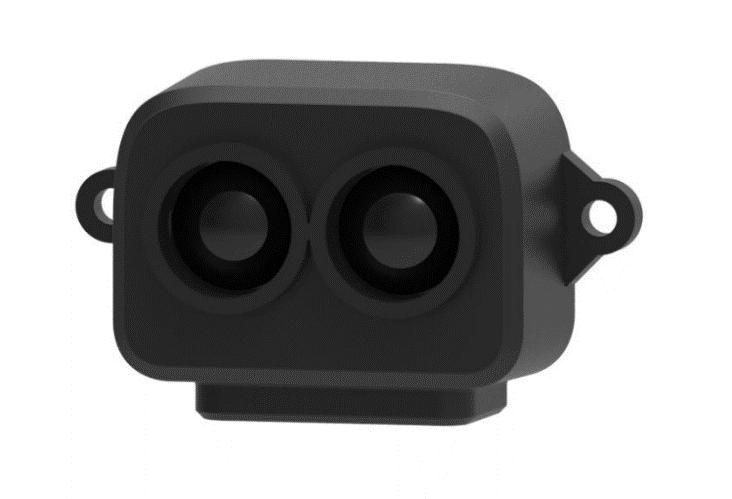
Benewake (Beijing) Co., Ltd
PREFACE
Dear users: Thank you for choosing Benewake products. For the purpose of offering better operation experience to you, we hereby write this manual for an easier and simpler operation of our product, hoping to better solve the common problems you may meet. This user manual contains the relevant information on product introduction, usage and maintenance of TF-Luna, covers the product operation introduction and common problem solutions. Please read this manual carefully before using the product. Remember the precautions to avoid hazards, and please follow the described steps in the manual when using it. If you have any problems in the process of usage, you are welcome to contact Benewake at any time for help.
Contact Details Official website: https://ai.benewake.com/zh/products/tf-luna/ TEL : +86-10-5745 6983 Technical questions , please contact : support@benewake.com Consult sale information or request brochure , please contact : bw@benewake.com Headquarters Address Benewake (Beijing) Co., Ltd. 3rd Floor, Haiguo Jiaye Sci-Tech Park, Haidian District, Beijing, China Copyright Statement This User Manual is copyright © of Benewake. Please do not modify, delete or translate the description of this manual contents without the official written permission from Benewake.
Disclaimer As our products are constantly improving and updating, the specifications of TF-Luna are subject to change. Please refer to the official website for latest version.
CONTENTS
1 REVISIONS...............................................................................................................................................1 2 CAUTIONS...............................................................................................................................................2 2.1 About document.........................................................................................................................2 2.2 About product.............................................................................................................................2
| Parameter | Value |
|---|---|
| 2.3 Common errors and other notes | ................................................................................................ 2 |
| 3 PRINCIPLE DESCRIPTION AND KEY PARAMETERS | ..................................................................................3 |
| 3.1 Ranging Principle | ........................................................................................................................ 3 |
| 3.2 Basic Characteristic Parameters | ................................................................................................3 |
| 4 APPEARANCE AND STRUCTURE | ............................................................................................................. 4 |
4.1 Dimensions.................................................................................................................................. 4
| Parameter | Value |
|---|---|
| 5 ELECTRICAL CHARACTERISTICS | ............................................................................................................ 5 |
| 6 FUNCTIONAL DESCRIPTIONS AND CONFIGURATION | ........................................................................... 6 |
| 6.1 Description about Line Sequence and Connection | .................................................................. 6 |
| 6.2 Serial Port Communication Protocol | .......................................................................................... 6 |
| 6.3 I 2 C Communication | ..................................................................................................................... 7 |
| 6.4 Basic Data Output | ......................................................................................................................7 |
| 6.5 Continuous Ranging Mode | ......................................................................................................... 8 |
6.6 Trigger Mode............................................................................................................................... 8 6.7 On/off Mode............................................................................................................................... 8 6.8 Amp Threshold............................................................................................................................ 8 6.9 Distance Limit..............................................................................................................................9
| Parameter | Value |
|---|---|
| 6.10 Power Saving Mode | .................................................................................................................. 9 |
| 6.11 Ultra-low Power Mode | ..............................................................................................................9 |
| 6.11.1 Ultra-low Power Mode with Serial Port Communication | ............................................10 |
| 6.11.2 Ultra-low Power Mode with I | 2 C communication .........................................................10 |
| 6.11.3 Caveats | ........................................................................................................................11 |
| 6.12 Single Frequency Mode | .......................................................................................................... 11 |
| 6.13 Additional notes | ......................................................................................................................11 |
7 QUICK TEST GUIDE...............................................................................................................................12 7.1 Required tools for testing......................................................................................................... 12 7.2 Steps..........................................................................................................................................12 8 FIRMWARE UPGRADE........................................................................................................................... 14 APPENDIX I SERIAL PORT OUTPUT FORMAT........................................................................................... 15
1. 9-byte/cm (Default)....................................................................................................................15
2. PIX................................................................................................................................................ 15
3. 9-byte/mm..................................................................................................................................15
4. 32-byte with timestamp............................................................................................................. 15
5. ID-0 output................................................................................................................................. 15
6. 8-byte/cm...................................................................................................................................15
| Parameter | Value |
|---|---|
| 7. Output with Device ID | .................................................................................................................16 |
| Appendix II Serial communication protocol | ........................................................................................... 17 |
| 1. Version information ID_GET_VERSION=0x01 | .............................................................................. 17 |
| 2. System software restore ID_SOFT_RESET=0x02 | ........................................................................17 |
| 3. Output frequency ID_SAMPLE_FREQ=0x03 | ............................................................................... 17 |
| 4. Trigger mode ID_SAMPLE_TRIG=0x04 | ....................................................................................... 17 |
| 5. Output format setting ID_OUTPUT_FORMAT=0x05 | ...................................................................18 |
| 6. Baud rate setting ID_BAUD_RATE=0x06 | ....................................................................................18 |
| 7. Enable/disable output ID_OUTPUT_EN=0x07 | ........................................................................... 19 |
| 8. Enable/disable checksum comparison ID_FRAME_CHECKSUM_EN=0x08 | ...............................19 |
| 9. I 2 C slave machine address configuration ID_I | 2 C_SLAVE_ADDR=0x0B ..................................... 19 |
| 10. Restore default setting ID_RESTORE_DEFAULT=0x10 | ............................................................. 20 |
| 11. Save current setting ID_SAVE_SETTINGS=0x11 | ........................................................................ 20 |
| 12. Output product bar code ID_READ_MANU_BIN=0x12 | ............................................................. 20 |
| 13. Get full-length version number ID_GET_FULL_VERSION=0x14 | ................................................ 20 |
| 14. Amp threshold setting ID_AMP_THRESHOLD=0x22 | ................................................................. 21 |
| 15. Switch between Single Frequency and Dual Frequency ID_ DEALIAS_EN =0x29 | ................... 21 |
| 16. Timestamp synchronization ID_TIMESTAMP_SYNC =0x31 | ....................................................... 21 |
| 17. Enable/disable Power saving mode (ECO) ID_LOW_CONSUMPTION=0x35 | ..........................22 |
| 18. Filter Setup ID_FILTER_BIT_MAP=0x39 | ......................................................................................22 |
| 19. Distance limit setting ID_DIST_LIMIT=0x3A | .............................................................................. 22 |
| 20. Enable/disable on-off mode ID_ON_OFF_MODE=0x3B | ......................................................... 23 |
| 21. Read config by id ID_GET_CONFIG_PARA=0x3F | .....................................................................23 |
| 22. Ultra-low Power Mode ID_ ULTRA_LOW_POWER_MODE=0x58 | ............................................. 23 |
| 23. Frequency Calibration ID_FREQ_CNT_CALIB=0x59 | .................................................................23 |
| Appendix III I 2 C REGISTER TABLE | ............................................................................................................ 25 |

REVISIONS
1 REVISIONS
Version No. History Date A00 Original 2024.7.24
CAUTIONS
2 CAUTIONS
2.1 About document product. This manual provides all essential information you may need during the usage of this fully understand the contents of the manual. Please read this manual carefully before using this product and make sure that you 2.2 About product only original spare parts are permitted to use for performance and safety reasons. The product can only be maintained and repaired by qualified professionals, and and supply power according to the instructions. This product DOES NOT have polarity and over-voltage protection at all. Please wire The working temperature of the product is from -10℃ to 60℃, please do not use it outside this temperature range to avoid risk and damage. The storage temperature of the product is from -20℃ to 75℃, please do not store it outside this temperature range to avoid risk and damage. For safety and performance, please DO NOT open the product casing or remove the IR-pass filter. 2.3 Common errors and other notes milk liquid. Detecting object with high reflectivity, such as mirrors, smooth floor tiles, and calm Blocking the product with any transparent objects, such as glasses. The product’s lens may be covered by dusts or dirt which may affect results, so please keep the lens clean. The exposed circuit board is electrostatic sensitive. Please do not touch the circuit board of the product barehanded. Please use ESD wrist strap or antistatic gloves to ground yourself if any operation is necessary; Otherwise, the product may be damaged by static electricity.
PRINCIPLE DESCRIPTION AND KEY PARAMETERS
3 PRINCIPLE DESCRIPTION AND KEY PARAMETERS
3.1 Ranging Principle TF-Luna is using Time of Flight (ToF) principle to measure the distance and it periodically emits near infrared modulated waves. TF-Luna calculates the time by measuring the phase difference between the original wave and the reflection wave and uses that time to get relative distance, as shown in Figure 1.
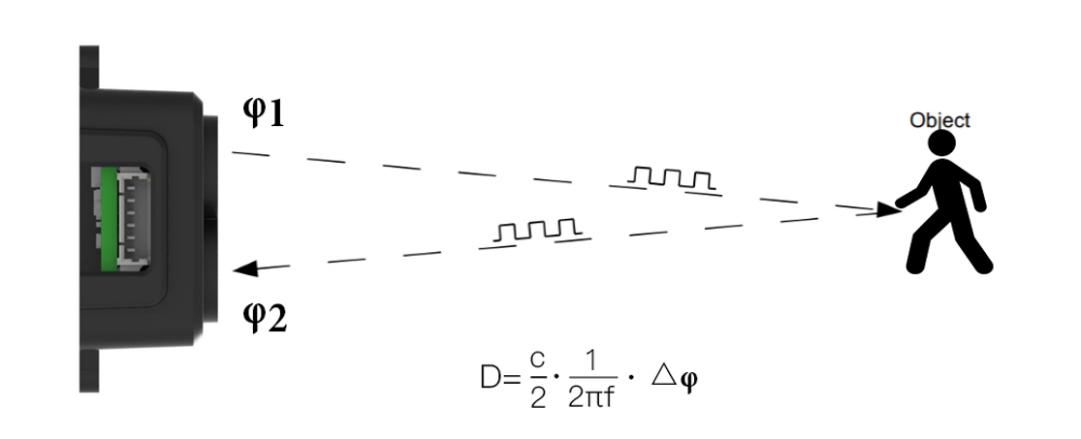
Figure 1 Schematics of ToF Principle
3.2 Basic Characteristic Parameters Table 1 Parameters specification of TF-Luna
| Parameter | Value |
|---|---|
| Description | Parameter value |
| Operating range | 5cm~55cm 1 |
| Accuracy | <3 cm 1 |
| Measurement unit | cm (Default) |
| Range resolution | 1cm |
| Frame rate | 1-250Hz 2 |
FoV 2° 3
1. The measurement distance is test with outdoors underwater, with the target object
| Parameter | Value |
|---|---|
| being common swimming pool wall tiles, under | 25 ℃ conditions, |
| 2 . The Highest frame rate is | 250 Hz, the default frame rate is 100Hz. The customized |
| update rate should be calculated by the formula: | 500 /n (n is more than 2 ), |
3. This is a theoretical reference value.
APPEARANCE AND STRUCTURE
4 APPEARANCE AND STRUCTURE
4.1 Dimensions
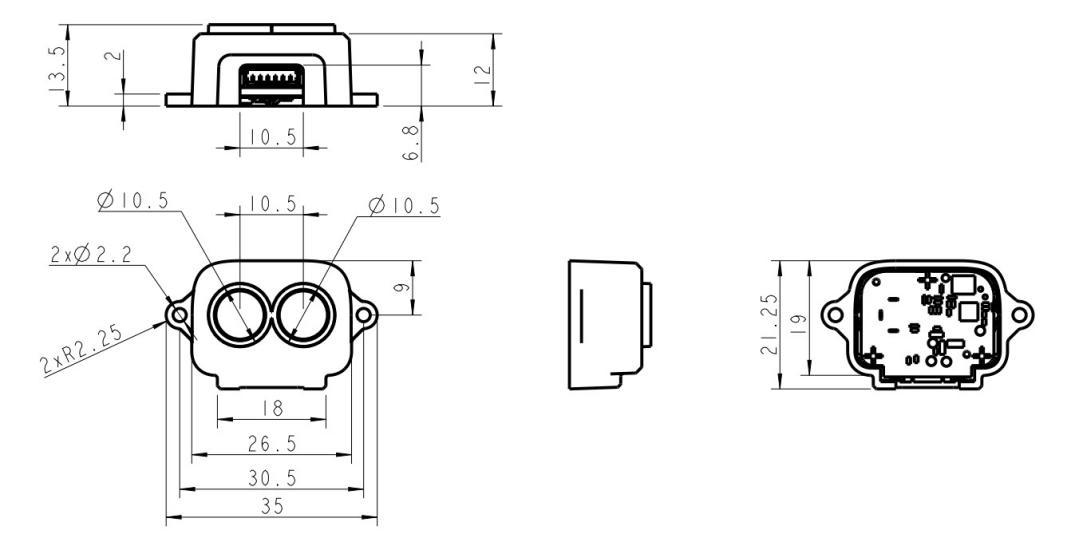
Figure 3 TF-Luna appearance and size drawing
ELECTRICAL CHARACTERISTICS
5 ELECTRICAL CHARACTERISTICS
Table 5 Major Electrical Parameters of TF-Luna
Description Value range Power supply voltage 3.7V-5.2V Average current ≤70mA Peak current 150mA Power consumption ≤350mW Communication signal level LVTTL (3.3V)
This product has no over-voltage nor polarity protection, so please make sure that the product is well connected, and the power supply voltage is inside the given range.
FUNCTIONAL DESCRIPTIONS AND CONFIGURATION
6 FUNCTIONAL DESCRIPTIONS AND CONFIGURATION
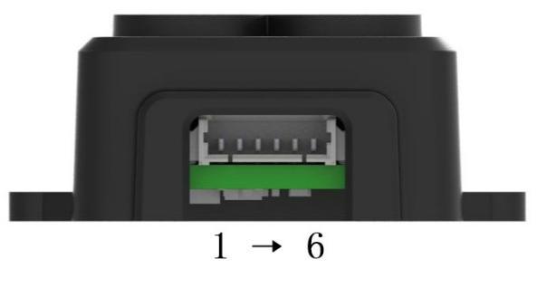
Figure 4 TF-Luna’s pin numbers
6.1 Description about Line Sequence and Connection Table 6 The Function and Connection Description of Each Pin
| Parameter | Value |
|---|---|
| No. Function | Description |
| 1 +5V | Power supply |
| 2 RXD/SDA | Receiving/Data |
| 3 TXD/SCL | Transmitting/Clock |
| 4 GND | Ground |
| 5 Configuration Input | Disconnected/3.3V: Serial port Communications mode Ground: I ² C mode |
| 6 Multiplexing output | I ² C mode: Data ready signal On/off mode: Output |
6.2 Serial Port Communication Protocol Serial port communication starts when pin 5 is disconnected or connected to 3.3v. It will set TF-Luna receiving RXD on pin 2 and sending TXD on pin 3. The serial port
communication protocol is defined as follows: 8 data bits, 1 stop bit with no parity check and default baud rate of 115200 bps.
Serial port communication protocol data byte format:
byte 0 1 2 3~Len-2 Len-1 Description Head(0x5A) Len ID Payload Checksum
Head: Fixed 0x5A. Len: The length of bytes from the head byte to check-sum at the end, and it has to be in between 4 to 255. ID: Indicates how to parse the payload data. Payload: Payload data segment, optional. Checksum: The lower 8 bytes of the sum from Head to Payload. Please check Appendix II Serial communication protocol for more information. Note: TF-Luna does not enable checksum check for sending data frames by default, that is, the Checksum at the end of the sending frame can be filled with any value. Thus, ANY value is acceptable on the Checksum byte, unless checking of those bytes is required. Please check “Enable/disable checksum comparison ID_FRAME_CHECKSUM_EN=0x08” in Appendix II Serial communication protocol to enable the feature.
FUNCTIONAL DESCRIPTIONS AND CONFIGURATION
The instruction makes change immediately after sending, but the current setting is not saved and will be lost after reboot. User must use “Save current setting ID_SAVE_SETTINGS=0x11” to save the change. The full save-current-setting hexadecimal sequence is 5A 04 11 00 in this case. 6.3 I 2 C Communication When pin 5 is connected to ground, TF-Luna enters I data and pin 3 is the SCL clock sending data. TF-Luna supports up to 400kps clock speed 2 C mode, then its pin 2 is used as SDA as slave machine and its default address is 0x10. For more information about I table refer to Appendix III I 2 C register table. 2 C register Note: In this document, the address of I [0x08, 0x77] ([08, 119] in decimal). For the first byte after I 2 C slave device is a 7-bit value with value range 2 C releases a start signal, the 7-bit address should be shifted leftward for one bit (i.e. multiplied with 2), and then filled with the read-write sign on the lowest bit. For TF-Luna, the default address of slave device is 0x10, the address for write operations is 0x20, and the address for read operations is 0x21.
| Parameter | Value |
|---|---|
| Write register timing: Start Slave Addr W Ack Register Addr | Ack Data1 Ack … DataN Ack Stop |
| Read register timing: Start Slave Addr | W Ack Register Addr Ack Stop |
| Start Slave Addr | R Ack Data1 Ack … DataN Nack Stop |
Note that in the read register sequence, the host can directly generate the second Start signal without generating the first Stop signal. The last Nack can also be an Ack signal. In the continuous ranging mode, the host must monitor pin 6 for synchronous signal and initiate the read data operation in time. Otherwise, it may cause an error by reading and updating the data register at the same time. In multi-machine bus mode, use command to trigger reading is strongly recommended.
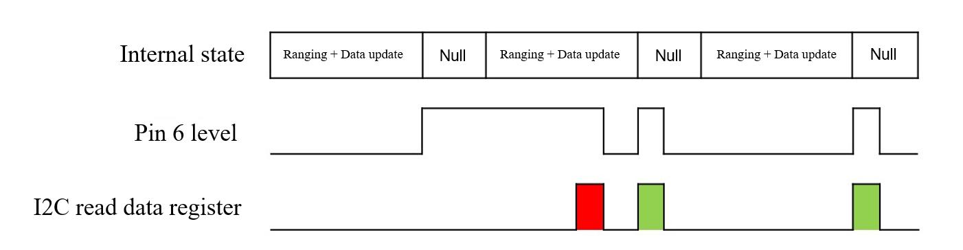
Pin 6 is normal low level and it switches to high as soon as the data is updated. It switches Figure 5 Timing of reading data register in I ² C mode to low level only if a read operation on any register is done. Therefore, I the register when receive a high level on pin 6 in the continuous ranging mode. As the 2 C host must read figure has shown above, the first result in red is unreliable and the rest two in green are accurate. After a write operation on the I need to read the value from the register for validation purposes, we recommend waiting 2 C register, it takes TF-Luna some time to process. If users for 100ms after the write operation, prior to the next read operation. 6.4 Basic Data Output TF-Luna normally provides these data below: Distance (Dist): Default in centimeters. overexposed (Amp = 0xFFFF) or too low (Amp < 100). Normally, Amp value should not be Signal strength (Amp): Distance value is unreliable when receiving signal is above 30000. When Amp is above 32768, it indicates that TF-Luna has detected an ambient light overexposure, for instance, when it faces the sun in outside.
FUNCTIONAL DESCRIPTIONS AND CONFIGURATION
Chip Temperature (Temp): Celsius degree = Temp/ 8 - 256℃ TF-Luna supports various serial format, please check Appendix I Serial port output format for more information, and the default setting is 9-bytes/centimeter. Format setting is in “Output format setting ID_OUTPUT_FORMAT=0x05” section. 6.5 Continuous Ranging Mode TF-Luna will keep tracking the distance 500 times per second, but as the customized output frequency is lower, the output may take the average. For instance, if the output frequency is 100Hz as default, then the output values are the average (arithmetic mean) of 5 previous range data. Therefore, lower output frequency gives less time of the averaging process as well as less fluctuation of the output. The highest output frequency that TF-Luna supports is 250Hz (output_frequency ≤ 250Hz), and it must be 500/n Hz (where n is an integer that is in the range [2, 500]). Thus, all supported values of output frequency are: 250Hz, 166Hz, 125Hz, 100Hz, …, 2Hz, 1Hz. User can change the output frequency using “Output frequency ID_SAMPLE_FREQ=0x03”. 6.6 Trigger Mode TF-Luna enters trigger mode if the output frequency is set to 0 with “Output frequency ID_SAMPLE_FREQ=0x03”. In this mode, TF-Luna stops measuring and outputting unless it is triggered by “Trigger mode ID_SAMPLE_TRIG=0x04” — in other words, TF-Luna measures and output once as soon as it receives the hexadecimal byte string 5A 04 04 00. 6.7 On/off Mode object. TF-Luna can start On/off mode is designed from those users who only need to detect the existence of an this mode using “Enable/disable on-off mode ID_ON_OFF_MODE=0x3B” and then shows result through pin 6. Figure 6 below shows how the mode works when a high level is set to represent an object is detected.
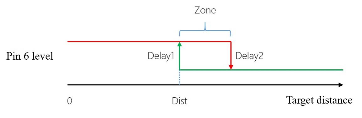
Zone value: If an object is detected closer than Dist, then Pin 6 outputs high-level, but Figure 6 On/off mode that high level means closer only if an object is detected farther than Dist + Zone, then Pin 6 outputs low-level. When zone is set to 0, pin 6 may output up and down cause by fluctuation of the measuring when the real distance happens to be the same as Dist. That is why a proper zone value is needed to help avoid this situation by having a hysteretic interval. Delay is also supported to avoid inaccurate jumping output. Pin 6 changes its output depends on the Dist value condition and the time it lasts. Delay1(ms) and Delay2(ms) determine how long that approaching changes and leaving changes should wait after Dist value is already over the line. Note: Since the Dist value is set to 0 under factory setting when no object is detected and Amp is too low, then pin 6 may have false output in the on/off mode. Please follow the instructions in 6.8 Amp to set the over-threshold value greater than Dist + Zone to avoid false output. 6.8 Amp Threshold The distance calculation may get false result if the Amp value is too low, so TF-Luna set the Dist value to dummy_dist(Default 0) when Amp is lower than amp_threshold (Default
FUNCTIONAL DESCRIPTIONS AND CONFIGURATION
100). If a user needs to change the Amp threshold value, please follow instructions in “Amp threshold setting ID_AMP_THRESHOLD=0x22”. Note that the final Amp threshold in TF-Luna is 10 times the value you send to it. 6.9 Distance Limit TF-Luna has a default maximum and minimum distance output: [min, max] = [0cm, 900cm]. User can change the output limits using “Distance limit setting ID_DIST_LIMIT=0x3A”. Note: Any distance value lower than 20cm or greater than 800cm may be unreliable. 6.10 Power Saving Mode The power consumption of TF-Luna is determined by two factors: the light source driving current and the light-emitting duty cycle. TF-Luna adjusts the driving current of the light source adaptively to achieve the purpose of large dynamic range adapting to different distances and different reflectivity targets. When the signal strength is too high, it will automatically switch to low gear current work. On the contrary, when the signal strength is too low, it will automatically switch to high gear current work. The higher the current gear is, the greater the power consumption will be. Refer to "6.5 Continuous Ranging ". In continuous ranging mode, TF-Luna always emits light with the highest duty cycle, which does not change with the output frequency. Therefore, when TF-Luna is in continuous working mode and the current gear is at the highest gear, the power consumption is the largest. When the power is supplied with 5V, the power consumption is about 350mW. The user can change TF-Luna's luminous duty cycle in two ways. The first is to use the command trigger mode. TF-Luna does not emit light when it does not receive a ranging command. At this time, the power consumption is about 42.5mW (5V power supply). The actual power consumption is determined by the frequency of the command trigger. Another way is to enable the low power consumption mode provided by TF-Luna. The internal working mechanism of this mode is the same as the command trigger mode, except that the trigger signal is automatically generated internally by TF-Luna. The user can set the TF-Luna to enter the low-power mode through the "Enable/disable Power saving mode (ECO) ID_LOW_CONSUMPTION=0x35" instruction. To ensure the internal working sequence of TF-Luna, the maximum output frequency of low power consumption mode is 10Hz. The following table lists the reference values of the average power consumption at different operating frequencies in the low power mode when the power supply is 5V. The actual power consumption may be affected by the ambient temperature or the supply voltage, and may differ from the reference value. Power saving
| Parameter | Value |
|---|---|
| frequency | Avg current(mA) Avg power (mW) |
| 1 Hz | 8.85 44.25 |
| 2 Hz | 9.2 46 |
| 3 Hz | 9.55 47.75 |
| 4 Hz | 9.9 49.5 |
| 5 Hz | 10.25 51.25 |
| 6 Hz | 10.6 53 |
| 7 Hz | 10.95 54.75 |
| 8 Hz | 11.3 56.5 |
| 9 Hz | 11.65 58.25 |
| 10 Hz | 12 60 |
6.11 Ultra-low Power Mode In order to further reduce power consumption, TF-Luna offers an Ultra-low Power Mode. In this mode, MCU enters sleep mode, and the standby power consumption of TF-Luna is
FUNCTIONAL DESCRIPTIONS AND CONFIGURATION
about 1.5mW at this time. However, when MCU sleeps, it is not able to automatically awake as Low Power Mode is activated. Therefore, we need to change the voltage of Pin 2 to wake it up. 6.11.1 Ultra-low Power Mode with Serial Port Communication (1) The command “Ultra-low Power Mode ID_ ULTRA_LOW_POWER_MODE=0x58” is used to Turn on Ultra-low Power Mode turn on Ultra-low Power Mode. TF-Luna will stop serial port outputting data once the command is delivered. However, it will not enter the mode immediately. Users should send “Save current setting ID_SAVE_SETTINGS=0x11” to save current settings and then send “System software restore ID_SOFT_RESET=0x02” to reset system. Later on, TF-Luna will enter the Ultra-low Power Mode. Since the settings have been saved, TF-Luna will enter directly into this mode on next boot-up. (2) Users can wake up TF-Luna and make it perform range-finding once by sending a Bring up Range-finding random byte to the serial port. TF-Luna will send back the range-finding result in a specific format, and then enter Ultra-low Power Mode once again. The following graph shows the case in which the baud rate is 115200 with 9-byte output format. The awakening lasts about 8.5ms.

(3) Figure 7 Time sequence of Ultra-low Power Mode with serial port communication Users cannot exit the Ultra-low Power Mode directly, because the serial port Turn off Ultra-low Power Mode communication module is disabled. TF-Luna can only receive serial port commands during short intervals when it is awake. Therefore, users need to continuously send the command “Ultra-low Power Mode ID_ ULTRA_LOW_POWER_MODE=0x58” to disable the Ultra-low Power Mode untill TF-Luna responds. After that, users should send “Save current setting ID_SAVE_SETTINGS=0x11” command to save current settings. (4) TF-Luna consumes 1.5mW during sleep and on average 260mW during awakening. The Estimation of Power Consumption awakening will last about 8.5ms. Based on the information, it consumes on average 3.7mW if we wake it up every second and on average 1.72mW if we wake it up every ten seconds. 6.11.2 Ultra-low Power Mode with I 2 C communication (1) In order to turn on and save Ultra-low Power Mode, users need to write three consecutive Turn on Ultra-low Power Mode bytes [0x01, 0x01, 0x02] to the address 0x1F. (2) Users can attempt reading any one of valid or invalid register addresses (which will not Bring up Range-finding make us receive ACK from the slave device). In this way, TF-Luna will detect the change of voltage on Pin 2 and thus it will be awakened. TF-Luna will perform range-finding once
FUNCTIONAL DESCRIPTIONS AND CONFIGURATION
upon each awakening, and update the result on the register. It will not fall back to sleep mode until the user performs a read-register operation.
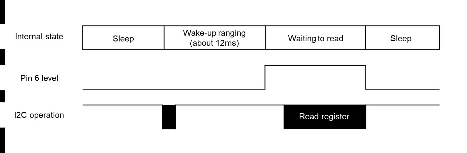
(3) Figure 8 Time sequence of Ultra-low Power Mode with I 2 C communication Reading the register will make TF-Luna enter sleep mode once again, therefore, in order Turn off Ultra-low Power Mode to turn off the Ultra-low Power Mode, users need to write three consecutive bytes [0x00, 0x01, 0x02] to the address 0x1F after the awakening. It should be done no sooner than 6ms after the awakening). (4) TF-Luna consumes 1.5mW during sleep and on average 200mW during awakening. Estimation of Power Consumption Range-finding in an awakening period takes about 12ms, and awaiting users’ read-operation consumes about 42.2mW. Assuming it waits for 5ms, based on the information, it consumes on average 4.1mW if we wake it up every one second, and on average 1.76mW if we wake it up every ten seconds. 6.11.3 Caveats Users should not send any setup command in the Ultra-low Power Mode, because MCU will be in sleep so that it may not respond to users’ command. In Ultra-low Power Mode, it is only allowed to bring up range-finding, or to turn off the mode. All other operations should be performed after the mode is turned off. 6.12 Single Frequency Mode TF-Luna obtains distance measurement from phase shift of the sinusoidal modulated laser light. The model is subjected to the “periodic distance” problem. The periodic distance for TF-Luna is 15 meters, when working in Single Frequency Mode. However, when the distance is beyond 15 meters, the measured value starts from zero again. Assuming there is a highly reflective object at 16 meters; TF-Luna may mistake it as at 1 meter. In order to extend the periodic distance, TF-Luna sets the default work mode to Dual Frequency Mode. The periodic distance in such a mode is over 65 meters, far wider than the sensor’s measuring range. In this way, the “overshoot” problem is addressed. However, in Dual Frequency Mode, the range-finding algorithm requires higher stability on sensor data. When the signal is weak (AMP lower than 100), the low data stability produces errors in the range algorithm, and thus yields anomalies in output range values. The error can reach tens of meters. In some application scenarios, the target reflection rate is low so that AMPs lower than 100 are needed. In this case, users can set TF-Luna to Single Frequency Mode. In Single Frequency Mode, when AMP is lower than 100, the stability of range data is low. Even so, it is not allowed to have significant anomalies on data values. Meanwhile, users should make sure their application scenarios are not subjected to the overshoot problems. 6.13 Additional notes Please check Appendix II Serial communication protocol for more options, such as version ID report, system software restore, baud rate configuration, etc.
QUICK TEST GUIDE
7 QUICK TEST GUIDE
7.1 Required tools for testing
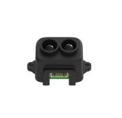
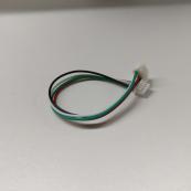
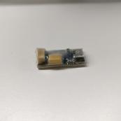
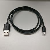

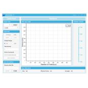
TF-Luna Data cable TTL to USB convertor USB cable PC software PC 7.2 Steps Please visit our official website (https://ai.benewake.com/zh/products/tf-luna/) and download the test software of 1 Download and install the latest test software TF-Luna. Note: Please turn off any anti-virus software before uncompressing the PC software. Some anti-virus software may regard the ‘.exe’ file as virus. Also, released versions are only running on windows systems currently. 2 Connecting hardware and cables
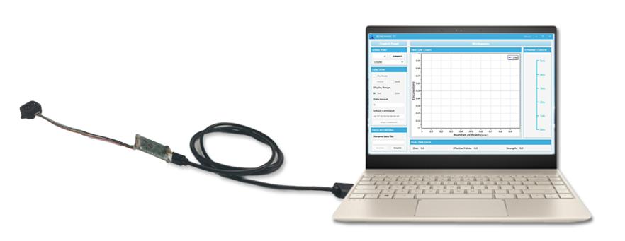
Please connect TF-Luna, TTL-USB converter, and USB cable properly as shown in Figure 9. Figure 9 Schematic Diagram of Correct Connection Please check if there is any loose connection, and then plug the USB cable into your PC. Open your test software and check data output Open the PC software and select “ 3 ① TF-Luna” and select automatically recognized occupied serial port (in this case “ ② COM9”) as shown in Figure 10.
QUICK TEST GUIDE
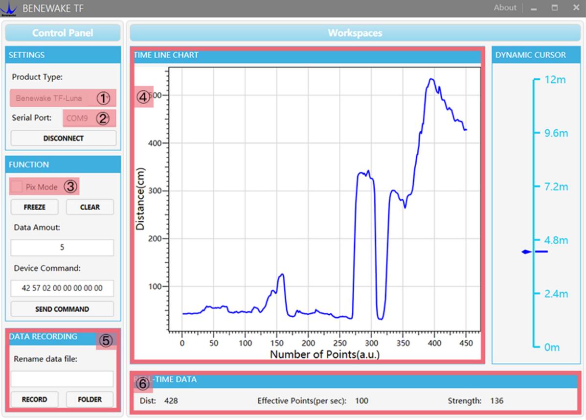
Now click the “CONNECT” button, and a continuous images of the output data will be Figure 10 PC software Interface and Display displayed in area “ The real-time data of the Current measure distance (Dist), effective data points per ④ TIME LINE CHART” on the right if everything is connected successfully. second (Effective Points) and signal strength (Strength) will be displayed in area “ TIME DATA” below as well. ⑥ REAL
Notes: a) If nothing is displayed in area “ ④ TIME LINE CHART”, please check the wire connection
and sequence. A red LED indicator inside the transmitting lens at front will light up when TF-Luna is power-on. b) Please select “ avoid abnormal data display in the “ ③ Pix Mode” before switching TF-Luna’s outputs to Pixhawk format to TIME LINE CHART” area. Note that selecting Pix Mode will automatically set the unit of distance to meters. ④ c) centimeters as distance unit, the distance unit displayed in the chart remains the same as Since TF-Luna does not pass unit information and the software always uses centimeter even if TF-Luna output in millimeter. For instance, suppose the actual measurement is one meter and the distance value from TF-Luna is 1000 mm, then the value read by the PC software is 1000. Thus, the software will display 1000 with unit cm.
FIRMWARE UPGRADE
8 FIRMWARE UPGRADE
TF-Luna allows upgrading firmware remotely when current firmware no longer supports users’ new requirements. Please contact us for the additional remote upgrading software if any relevant firmware upgrades are available on Benewake official website.
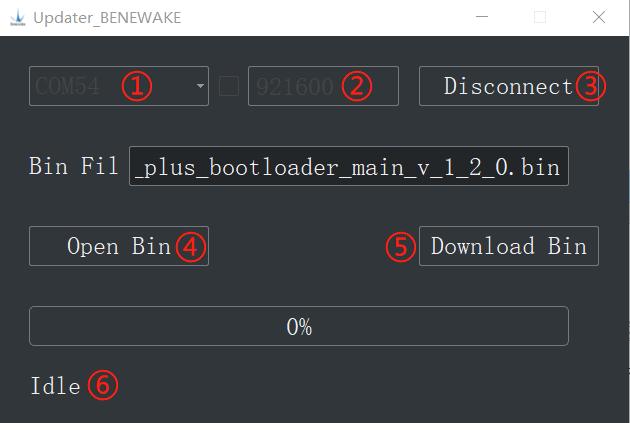
The tools for an upgrade are mostly the same as those in the Quick Test Guide, including Figure 11 Firmware Upgrade PC software of TF-Luna a TTL-USB convertor to connect TF-Luna with PC. Open the Updater.exe after connecting TF-Luna to your PC, and then select the correct port and baud rate, “ the updating firmware, then the file directory will be displayed in the textbox above. ① COM8” and “ ② 115200” in this case. Click “ ④ Open Bin” to choose Finally, click “ show up in “ ⑤ ”. Download Bin” to start upgrading and the upgrading information will Note: The full directory of the firmware files must use English letters only. ⑥
APPENDIX I SERIAL PORT OUTPUT FORMAT
APPENDIX I SERIAL PORT OUTPUT FORMAT
1. 9-byte/cm (Default) This format is supported for any firmware after Ver. 0.0.5 Byte 0 1 2 3 4 5 6 7 8 Description 0x59 0x59 Dist_L Dist_H Amp_L Amp_H Temp_L Temp_H Check_sum Dist: cm Amp: Signal strength indicator. Dist value is unreliable when Amp < 100 or Amp = 65535 (Overexposure) Temp: Celsius temperature = Temp / 8 - 256℃
2. PIX This format is supported for any firmware after Ver. 0.0.5 “X.YZ\r\n” is a sample ASCII string and only keep two significant digits in meter where “X.YZ” is the result.
3. 9-byte/mm This format is supported for any firmware after Ver. 0.0.5 byte 0 1 2 3 4 5 6 7 8 Descriptio n 0x59 0x59 Dist_L Dist_H Amp_L Amp_H Temp_L Temp_H Check_sum Dist: mm Amp: Signal strength indicator. Dist value is unreliable when Amp < 100 or Amp = 65535 (Overexposure) Temp: Celsius temperature = Temp / 8 - 256
℃
4. 32-byte with timestamp This format is supported for any firmware after Ver. 0.0.5 byte 0 1 2 3 4 5 6-9 10 Description 0x59 0x59 Dist_L Dist_H Amp_L Amp_H Timestamp Check_sum Dist: cm Amp: Signal strength indicator. Dist value is unreliable when Amp < 100 or Amp = 65535 (Overexposure) Timestamp: Timestamp (ms) is in small-end format
5. ID-0 output This format is supported for any firmware after Ver. 0.0.5 byte 0 1 2 3 4 5 6 7-10 11 Description 0x5A Len 0x00 Dist_L Dist_H Amp_L Amp_H Timestamp Check_sum Dist: cm Amp: Signal strength indicator. Dist value is unreliable when Amp < 100 or Amp = 65535 (Overexposure) Timestamp: Timestamp (ms) is in small-end format
6. 8-byte/cm T his format is supported for any firmware after Ver. 0.0.5
APPENDIX I SERIAL PORT OUTPUT FORMAT
byte 0 1 2 3 4-7 Description Dist_L Dist_H Amp_L Amp_H Timestamp
Dist: cm Amp: Signal strength indicator. Dist value is unreliable when Amp < 100 or Amp = 65535 (Overexposure) Timestamp: Timestamp (ms) is in small-end format
7. Output with Device ID This format is supported for any firmware after Ver. 3.0.8 byte 0 1 2 3 4 5 6 7-10 11 12 Descri ption 0x5 A 0x0 D 0x0 0 Dist_ L Dist_ H Amp_L Amp_ H Timestam p Dev_I d Check_sum Dist: cm Amp: Signal strength, if AMP is lower than 100, the range value is considered not reliable. Overexposure value is 65535 Timestamp : Timestamp (ms) is in little-endian format Dev_Id: device ID, same as the address of I 2 C slave device
Appendix II Serial communication protocol
Appendix II Serial communication protocol
1. Version information ID_GET_VERSION=0x01 This format is supported for any firmware after Ver. 0.0.5 Downward:
byte 0 1 2 Len-1 Description Head(0x5A) Len ID Check_sum
Upward:
byte 0 1 2 3~5 Len-1 Description Head(0x5A) Len ID *Version Check_sum
*Version: For instance, if the third, fourth, and fifth bytes are 112, 50, 9, then the version is 9.50.112 Sample instruction: [5A 04 01 00]
2. System software restore ID_SOFT_RESET=0x02 This format is supported for any firmware after Ver. 0.0.5 Downward
byte 0 1 2 Len-1 Description Head(0x5A) Len ID Check_sum
Upward byte 0 1 2 3 Len-1 Description Head(0x5A) Len ID *Status Check_sum *Status: 0 (success), otherwise (fail) Note: Any change without “save current setting” instruction will not be saved and will restore to original setting. Sample instruction: [5A 04 02 00]
3. Output frequency ID_SAMPLE_FREQ=0x03 This format is supported for any firmware after Ver. 0.0.5 Downward
| Parameter | Value |
|---|---|
| byte | 0 1 2 3~4 Len-1 |
| Description Head(0x5A) | Len ID Freq Check_sum |
| Default | 100 |
Freq: Working frequency if Freq > 0, and Trigger mode if Freq = 0. Upward
byte 0 1 2 3~4 Len-1 Description Head(0x5A) Len ID Freq Check_sum
Freq: The current working frequency of the LiDAR Sample instruction: 10Hz [5A 06 03 0A 00 00] 250Hz [5A 06 03 FA 00 00]
4. Trigger mode ID_SAMPLE_TRIG=0x04 This format is supported for any firmware after Ver. 0.0.5 Downward
Appendix II Serial communication protocol
byte 0 1 2 Len-1 Description Head(0x5A) Len ID Check_sum
Upward Data frame Sample instruction: [5A 04 04 00]
5. Output format setting ID_OUTPUT_FORMAT=0x05 This format is supported for any firmware after Ver. 0.0.5 Downward
| Parameter | Value |
|---|---|
| byte | 0 1 2 3 Len-1 |
| Description | Head(0x5A) Len ID Format Check_sum |
| Default | 0x01 |
Format: 0x01 = 9-byte/cm 0x02 = PIX 0x06 = 9-byte/mm 0x07 = 32-byte with timestamp 0x08 = ID-0 0x09 = 8-byte/cm 0x0A = Output with device ID Upward
byte 0 1 2 3 Len-1 Description Head(0x5A) Len ID Format Check_sum
Format: TF-Luna’s current output format setting Example: [5A 05 05 02 00] means PIX
6. Baud rate setting ID_BAUD_RATE=0x06 This format is supported for any firmware after Ver. 0.0.5 Downward
| Parameter | Value |
|---|---|
| byte | 0 1 2 3~6 Len-1 |
| Description | Head(0x5A) Len ID Baud rate Check_sum |
| Default | 115200 |
Upward
byte 0 1 2 3~6 Len-1 Description Head(0x5A) Len ID Baud rate Check_sum
Baud rate: TF-Luna’s current baud rate. Note: Only baud rate in [9600, 921600] are supported. Example: 9600 [5A 08 06 80 25 00 00 00] 19200 [5A 08 06 00 4B 00 00 00] 38400 [5A 08 06 00 96 00 00 00] 57600 [5A 08 06 00 E1 00 00 00] 115200 [5A 08 06 00 C2 01 00 00] 230400 [5A 08 06 00 84 03 00 00] 460800 [5A 08 06 00 08 07 00 00] 921600 [5A 08 06 00 10 0E 00 00]
Appendix II Serial communication protocol
7. Enable/disable output ID_OUTPUT_EN=0x07 This format is supported for any firmware after Ver. 0.0.5 Downward
| Parameter | Value |
|---|---|
| byte | 0 1 2 3 Len-1 |
| Description | Head(0x5A) Len ID Enable Check_sum |
| Default | 1 |
Enable: 0 to disable, 1 to enable. Upward
byte 0 1 2 3 Len-1 Description Head(0x5A) Len ID Enable Check_sum
Example: Enable output [5A 05 07 01 00] Disable output [5A 05 07 00 00]
8. Enable/disable checksum comparison ID_FRAME_CHECKSUM_EN=0x08 This format is supported for any firmware after Ver. 0.0.5 Downward
| Parameter | Value |
|---|---|
| byte | 0 1 2 3 Len-1 |
| Description | Head(0x5A) Len ID Enable Check_sum |
| Default | 0 |
Enable: 0 to disable, 1 to enable. Note: Even if the Downward data checksum comparison is disabled, the valid checksum is still included in the upward data frame Upward
byte 0 1 2 3 Len-1 Description Head(0x5A) Len ID Enable Check_sum
Example: Enable checksum comparison [5A 05 08 01 00] Disable checksum comparison [5A 05 08 00 67]
9. I 2 C slave machine address configuration ID_I 2 C_SLAVE_ADDR=0x0B This format is supported for any firmware after Ver. 1.0.0 Downward
| Parameter | Value |
|---|---|
| byte | 0 1 2 3 Len-1 |
| Description | Head(0x5A) Len ID I 2 c_slave_addr Check_sum |
| Default | 0x10 |
I Upward 2 c_slave_addr: range [0x08, 0x77]
byte 0 1 2 3 Len-1 Description Head(0x5A) Len ID I 2 c_slave_addr Check_sum
Example: Change to 0x20 [5A 05 0B 20 00]
Appendix II Serial communication protocol
10. Restore default setting ID_RESTORE_DEFAULT=0x10 This format is supported for any firmware after Ver. 0.0.5 Downward
byte 0 1 2 Len-1 Description Head(0x5A) Len ID Check_sum
Upward
byte 0 1 2 3 Len-1 Description Head(0x5A) Len ID Status Check_sum
Status: 0 for success, otherwise for errors Example: Restore default setting [5A 04 10 00]
11. Save current setting ID_SAVE_SETTINGS=0x11 This format is supported for any firmware after Ver. 0.0.5 Downward
byte 0 1 2 Len-1 Description Head(0x5A) Len ID Check_sum
Upward
byte 0 1 2 3 Len-1 Description Head(0x5A) Len ID Status Check_sum
Status: 0 for success, otherwise for errors Example: [5A 04 11 00]
12. Output product bar code ID_READ_MANU_BIN=0x12 This format is supported for any firmware after Ver. 0.0.5 Downward
byte 0 1 2 Len-1 Description Head(0x5A) Len ID Check_sum
Upward
byte 0 1 2 3-16 Len-1 Description Head(0x5A) Len ID Bin Check_sum
Bin: 14 byte product bar code Example: Send [5A 04 12 00] Receive: U0900018010001, then the code is from the third byte to the sixteenth: 0x55 0x30 0x39 0x30 0x30 0x30 0x31 0x38 0x30 0x31 0x30 0x30 0x30 0x31
13. Get full-length version number ID_GET_FULL_VERSION=0x14 This format is supported for any firmware after Ver. 0.0.5 Downward
byte 0 1 2 Len-1 Description Head(0x5A) Len ID Check_sum
Upward byte 0 1 2 3-10 1 12-19 2 21-22 2 24-25 2 27-28 Len-1
Appendix II Serial communication protocol
1 0 3 Minor 6 Revisio
Descripti Head (0x5A Le I Nam ‘.’ Branc ‘.’ Major versio ‘.’ versio ‘.’ n Check on) n D e h n No. n No. version No. _sum Example: [5A 04 14 00]
14. Amp threshold setting ID_AMP_THRESHOLD=0x22 This format is supported for any firmware after Ver. 0.0.5 Downward
| Parameter | Value |
|---|---|
| byte | 0 1 2 3 4-5 Len-1 |
| Description Head(0x5A) Len ID Amp_Threshold Dummy_Dist | Check_sum |
| Default | 10 0 |
Amp_Threshold: When Amp < Amp_Threshold * 10, then output Dummy_Dist instead of the result of calculation Dummy_Dist: The output distance when Amp is too low. Upward
byte 0 1 2 3 4-5 Len-1 Description Head(0x5A) Len ID Amp_Threshold Dummy_Dist Check_sum
Example: To output 500 cm when Amp < 300 [5A 07 22 1E F4 01 00]
15. Switch between Single Frequency and Dual Frequency ID_ DEALIAS_EN =0x29 This format is supported for any firmware after Ver. 0.0.5 Downward
| Parameter | Value |
|---|---|
| byte | 0 1 2 3 Len-1 |
| Description | Head(0x5A) Len ID Enable Check_sum |
| Default | 1 |
| Enable : 1 ( Dual Frequency Mode | ) 0 ( Single Frequency Mode ) |
Upward
byte 0 1 2 3 Len-1 Description Head(0x5A) Len ID Enable Check_sum
Example: Dual Frequency Mode [5A 05 29 01 00] Single Frequency Mode [5A 05 29 00 00]
16. Timestamp synchronization ID_TIMESTAMP_SYNC =0x31 This format is supported for any firmware after Ver. 0.0.5 Downward
| Parameter | Value |
|---|---|
| byte | 0 1 2 3-6 Len-1 |
| Description | Head(0x5A) Len ID Std Check_sum |
| Default | 0 |
Std: The current std timestamp specified Example: To set timestamp to 1000ms [5A 08 31 E8 03 00 00 00]
Appendix II Serial communication protocol
17. Enable/disable Power saving mode (ECO) ID_LOW_CONSUMPTION=0x35 This format is supported for any firmware after Ver. 0.0.5 Downward
| Parameter | Value |
|---|---|
| byte | 0 1 2 3-4 Len-1 |
| Description | Head(0x5A) Len ID Sample_rate Check_sum |
| Default | 0 |
Sample_rate: Work frequency if Sample_rate is positive (0 to disable power saving) Upward
byte 0 1 2 3-4 Len-1 Description Head(0x5A) Len ID Sample_rate Check_sum
Example: Enable power saving mode and measure at 10Hz frequency [5A 06 35 0A 00 00]
18. Filter Setup ID_FILTER_BIT_MAP=0x39 This format is supported for any firmware after Ver. 0.0.5 Downward
| Parameter | Value |
|---|---|
| byte | 0 1 2 3 Len-1 |
| Description | Head(0x5A) Len ID Filter_bit_map Check_sum |
| Default | 0x03 |
Filter_bit_map: Filter setup: 0 to disable, 1 to enable. Bit0 – Kalman Filter Bit1 – Median Filter Upward
byte 0 1 2 3 Len-1 Description Head(0x5A) Len ID Filter_bit_map Check_sum
Example: Filter off [5A 05 39 00 00] Filter on [5A 05 39 03 00]
19. Distance limit setting ID_DIST_LIMIT=0x3A This format is supported for any firmware after Ver. 0.0.5 Downward
| Parameter | Value |
|---|---|
| byte | 0 1 2 3-4 5-6 7 Len-1 |
| Description Head(0x5A) Len ID Dist_min Dist_max | Silence Check_sum |
| Default | 0 900 0 |
Dist_min: minimum distance output in centimeters. Dist_max: maximum distance output in centimeters. Silence: No output when the distance is out of range if silence = 1. Output limit when out of range if silence = 0 Upward
byte 0 1 2 3-4 5-6 7 Len-1 Description Head(0x5A) Len ID Dist_min Dist_max Silence Check_sum
Example: Output limit when out of range with the minimum set to be 20cm and the maximum set to be 500cm [5A 09 3A 14 00 F4 01 00 00]
Appendix II Serial communication protocol
20. Enable/disable on-off mode ID_ON_OFF_MODE=0x3B This format is supported for any firmware after Ver. 1.0.0 Downward
| Parameter | Value |
|---|---|
| byte | 0 1 2 3 4-5 6-7 8-9 10-11 Len-1 |
| Description Default Head(0x5A) | Len ID Mode Dist Zone Delay1 Delay2 Check_sum |
| Mode: 0 (Normal output), 1 (On-off mode with high level output when closer) , 2 (On-off | 0 0 0 0 0 |
mode with low level output when closer) Dist: critical dist value (the closer one) in centimeters. Zone: Zone size in centimeters Delay1: Delay time 1 in millisecond. Pin 6 switch level only if the distance detected is less than Dist and the situation last for Delay1 long. Delay2: Delay time 2 in millisecond. Pin 6 switch level only if the distance detected is more than Dist + Zone and the situation last for Delay2 long. Example: Enable on-off mode with high level output when closer, and set Dist = 200cm, Zone=10cm, Delay1 = Delay2 = 1000ms: [5A 0D 3B 01 CB 00 0A 00 E8 03 E8 03 00]
21. Read config by id ID_GET_CONFIG_PARA=0x3F This format is supported for any firmware after Ver. 0.0.5 Downward
byte 0 1 2 3 Len-1 Description Head(0x5A) Len ID Id Check_sum
Id: The same as we mentioned above. Upward: The same format of relevant Id. Example: Read output frequency [5A 05 3F 03 00]
22. Ultra-low Power Mode ID_ ULTRA_LOW_POWER_MODE=0x58 This format is supported for any firmware after Ver. 3.0.7 Downward
byte 0 1 2 3 Len-1 Description Head(0x5A) Len ID Enable Check_sum
Enable : 0 to disable, 1 to enable. Upward
byte 0 1 2 3 Len-1 Description Head(0x5A) Len ID Enable Check_sum
Example: Turn on Ultra-low Power Mode [5A 05 58 01 00] Turn off Ultra-low Power Mode [5A 05 58 00 00]. Since there is a time period in an Ultra-low Power Mode awakening phase, the turn-off command should be sent multiple times, e.g. [5A 05 58 00 00 5A 05 58 00 00 5A 05 58 00 00 5A 05 58 00 00 5A 05 58 00 00]
23. Frequency Calibration ID_FREQ_CNT_CALIB=0x59 This format is supported for any firmware after Ver. 3.0.7
Appendix II Serial communication protocol
Downward
byte 0 1 2 3 Len-1 Description Head(0x5A) Len ID Cmd Check_sum
Cmd : 1 (Execute frequency calibration, which takes about two seconds), 2 (Read frequency calibration parameters) Upward
byte 0 1 2 3-4 Len-1 Description Head(0x5A) Len ID Calib_freq_cnt Check_sum
Calib_freq_cnt : For frequency calibration parameters, a non-zero value indicates the completion of calibration Example: Execute frequency calibration [5A 05 59 01 00] Read frequency calibration parameters [5A 05 59 02 00]
Appendix III I2C REGISTER TABLE
| Parameter | Value |
|---|---|
| Appendix III I | 2 C REGISTER TABLE |
| Address R/W | Name Value Initial Description |
| 0x00 R | DIST_LOW -- cm |
| 0x01 R | DIST_HIGH -- |
| 0x02 R | AMP_LOW -- |
| 0x03 R | AMP_HIGH -- |
| 0x04 R | TEMP_LOW -- Unit: 0.01 Celsius |
| 0x05 R | TEMP_HIGH -- |
| 0x06 R | TICK_LOW -- Timestamp |
| 0x07 R | TICK_HIGH -- |
| 0x08 R | ERROR_LOW -- |
| 0x09 R | ERROR_HIGH -- |
| 0x0A R | VERSION_REVISION -- |
| 0x0B R | VERSION_MINOR -- |
| 0x0C R | VERSION_MAJOR -- |
| 0x0D-0x0F | -- Hold |
| 0x10-0x1D R | SN -- Production code in 14 bytes ASCI code (0x10 is the first byte) |
| 0x1E | -- Hold |
| 0x1F W | ULTRA_LOW_POWER -- 0x01: Ultra-low power mode 0x00: Normal |
| 0x20 W | SAVE -- Write 0x01 to save current setting |
| 0x21 W | SHUTDOWN/REBOOT -- Write 0x02 to reboot |
| 0x22 W/R | SLAVE_ADDR 0x10 Range: [0x08, 0x77] |
| 0x23 W/R | MODE 0x00 0x00: Continuous ranging mode 0x01: Trigger mode |
| 0x24 W | TRIG_ONE_SHOT -- 0x01: Trigger once (only on trigger mode) |
| 0x25 W/R | ENABLE 0x01 0x00: Turn off LiDAR 0x01: Turn on LiDAR |
| 0x26 W/R | FPS_LOW 0x64 |
| 0x27 W/R | FPS_HIGH 0x00 |
| 0x28 W/R | LOW_POWER 0x00 0x01: Power saving mode 0x00: Normal |
| 0x29 W RESTORE_FACTORY_DEFAULTS | -- Write 0x01 to restore factory default settings |
| 0x2A W/R | AMP_THR_LOW 0x64 Amp threshold value |
| 0x2B W/R | AMP_THR_HIGH 0x00 |
| 0x2C W/R | DUMMY_DIST_LOW 0x00 Dummy dist value |
| 0x2D W/R | DUMMY_DIST_HIGH 0x00 |
| 0x2E W/R | MIN_DIST_LOW 0x00 Minimum dist in mm, but not working on DUMMY_DIST |
| 0x2F W/R | MIN_DIST_HIGH 0x00 |
Appendix III I2C REGISTER TABLE
| Parameter | Value |
|---|---|
| 0x30 W/R | MAX_DIST_LOW 0x20 Maximum dist in mm, but not working on DUMMY_DIST |
| 0x31 W/R | MAX_DIST_HIGH 0x03 |
| 0x32-0x3B | -- Hold |
| 0x3C-0x3F R | SIGNATURE -- ‘L’ ’U’ ‘N’ ‘A’ |