
Technical documents
TFmini Plus User Manual
TFmini Plus User Manual

TFmini Plus User Manual
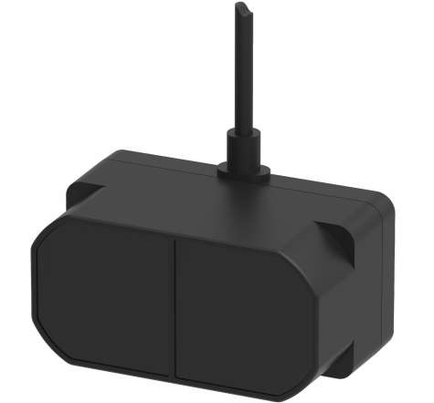
Benewake (Beijing) Co., Ltd
PREFACE
Dear users: Thank you for choosing Benewake products. For the purpose of offering better operation experience to you, we hereby write this manual for an easier and simpler operation of our product, hoping to better solve the common problems you may meet. This user manual contains the relevant information on product introduction, usage and maintenance of TFmini Plus, covers the product operation introduction and common problem solutions. Please read this manual carefully before using the product. Remember the precautions to avoid hazards, and please follow the described steps in the manual when using it.
If you have any problems in the process of usage, you are welcome to contact Benewake at any time for help.
Contact Details Official website: https://ai.benewake.com/en/products/tfmini-plus/ TEL:+86-10-57456983 Technical questions,please contact: support@benewake.com Consult sale information or request brochure,please contact: bw@benewake.com
Headquarters Address Benewake (Beijing) Co., Ltd. 3rd Floor, Haiguo Jiaye Sci-Tech Park, Haidian District, Beijing, China
Copyright Statement This User Manual is copyright © of Benewake. Please do not modify, delete or translate the description of this manual contents without the official written permission from Benewake.
Disclaimer As our products are constantly improving and updating, the specifications of TFmini Plus are subject to change. Please refer to the official website for latest version.
CONTENTS
1 ATTENTIONS ................................................................................................................ 1 1.1 About this Manual ................................................................................................ 1 1.2 Usage of Product .................................................................................................. 1 1.3 Conditions with Potential Malfunction ................................................................... 1 2 DESCRIPTION ............................................................................................................. 2 2.1 Product description ...............................................................................................2 2.2 Principle of Distance Measurement ....................................................................... 2 2.3 Key Characteristic Parameters ...............................................................................2 2.4 Repeatability ........................................................................................................ 3 2.5 Distance Measurement Characteristics .................................................................. 4 3 APPEARANCE AND STRUCTURE ...................................................................................6 3.1 Product Structure .................................................................................................. 6 4 ELECTRICAL CHARACTERISTICS ....................................................................................7 5 LINE SEQUENCE AND DATA COMMUNICATION PROTOCOL ............................................8 5.1 Description about Line Sequence and Connection ..................................................8 5.2 Serial port Communication Protocol ...................................................................... 8 5.3 Data Output Format of Serial port ..........................................................................9 5.4 Descriptions of default Output Data .......................................................................9 5.5 I2C data communication ......................................................................................10 5.6 Timing sequence description of I2C mode ............................................................10 5.7 I/O mode description .......................................................................................... 10 6 QUICK TEST .............................................................................................................. 12 6.1 Required Tools of Product Test ............................................................................ 12 6.2 Test Procedures .................................................................................................. 12 7 DESCRIPTIONS ON USER-DEFINED PARAMETER CONFIGURATION ............................... 15 7.1 Function Overview .............................................................................................. 15 7.2 Command Convention .........................................................................................15 7.3 Command Frame Definition .................................................................................15 7.4 General Parameter Configuration and Description ............................................... 16 8 REMOTE UPGRADING ................................................................................................20 9 MALFUNCTION: CAUSES AND TROUBLESHOOTING .....................................................21 10 Q&A ........................................................................................................................... 23 ATTACHMENT 1: INTRODUCTION OF TF SERIES PC SOFTWARE ............................................24

OVERVIEW
1 OVERVIEW
1.1 About this Manual This manual provides all the essential information during the usage of this product. Please carefully read this manual and make sure that you fully understand everything herein. 1.2 Usage of Product The maintenance of this product should be done by the professional technician, and the product can only work with the factory spare part for ensuring the performance and safety. This product itself has no polarity and over-voltage protection. Please properly connect and supply power as described in this manual. Operating temperature of this product is between -20℃ and 60℃. Do not use it beyond this temperature range to prevent malfunction. Storage temperature of this product is between -20℃ and 75℃. Do not store it beyond this temperature range to prevent malfunction. For ensuring the product performance, do not open the product shell or remove the IR-pass filter. 1.3 Conditions with Potential Malfunction Detecting object with high reflectivity, such as the mirror or the smooth floor tile, may cause a system malfunction. The product will malfunction if there is any transparent object between it and the detecting object, such as glass or water. The product will malfunction if its emitting or receiving IR-pass filter is covered by the dust. Please keep the IR-pass filters clean. Please do not spread ethyl alcohol on the IR-pass filters, which are made of acrylic, IR-pass filters will be damaged. Please do not pull the fine wire, the wire may be damaged.
DESCRIPTION
2 DESCRIPTION
2.1 Product Description TFmini Plus is a milestone of Benewake in the process of promoting the cost-effective -LiDAR. Apart from low-cost, small-size and low-power-consumption, TFmini Plus also improves the frame rate, introduces IP65 enclosures and optimizes various compensation algorithms. These new characters greatly expand the application fields and scenarios of TFmini Plus. The product is compatible with both the UART and I2C interface. Different interfaces can be switched by commands. 2.2 Principle of Distance Measurement TFmini Plus is based on ToF, namely, Time of Flight principle. To be specific, the product emits modulation wave of near infrared ray on a periodic basis, which will be reflected after contacting object. The product obtains the time of flight by measuring round-trip phase difference and then calculates relative range between the product and the detection object, as shown in Figure 1.
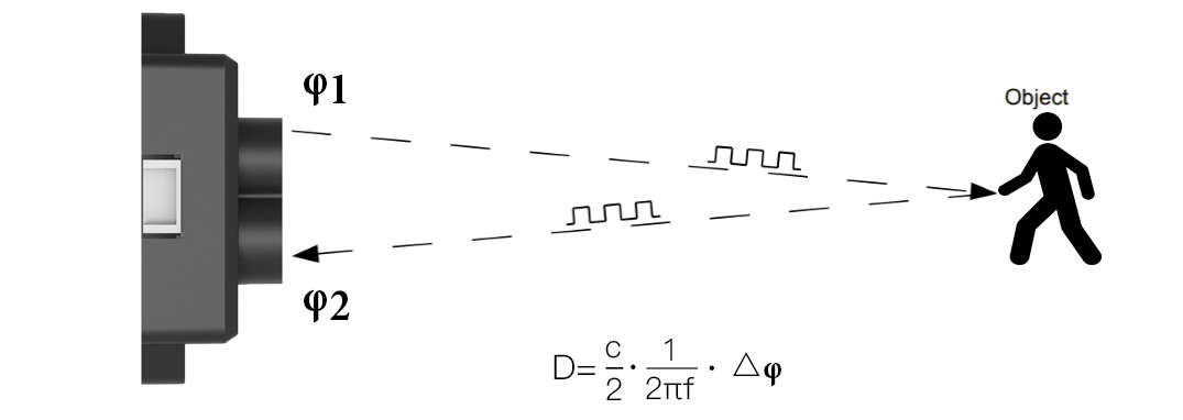
Figure 1 Schematics of ToF Principle
2.3 Key Characteristic Parameters Table 1 Key Characteristic Parameters of TFmini Plus
| Parameter | Value |
|---|---|
| Description | Parameter value |
| Operating range | 0.1m~12m ① |
| Accuracy | ±5cm@(0.1-5m) ② |
±1%@(5m-12m)
Measurement unit cm Range resolution 1cm
DESCRIPTION
FOV 3.6° ③ Frame rate 1~1000Hz(adjustable) ④
1 Operating range based on a standard whiteboard with reflectivity 90% in indoor condition 2 The distance measurement here is absolute accuracy, and the specific repeat accuracy will be described in the next section 2.4. 3 3.6°is the theoretical value, from which the actual value will be different. The theoretical divergence angle is 6°. 4 Only frame rates meeting the formula–1000/n (n is positive integer) can be set. The default frame rate is 100Hz. 2.4 Repeatability The TFmini Plus's range repeat accuracy is directly related to the strength value measured and the output frame rate (frequency). The ranging repeat accuracy is characterized by the standard deviation of ranging. The average ranging accuracy of the TFmini Plus can be estimated by the following formula: Distance_STD[cm] = p00 + p10∗x + p01∗y + p20∗x^2 + p11∗x∗y In the formula, x is log 10 Strengt ℎ, y is log 10 Frequence[Hz], p00, p01, p10, p20 and p11 are constant coefficients, and the values are as follows:
p00 = 0.9758 p01 = 1.175 p10 =− 0.6072 p20 = 0.09501 p11 =− 0.2904
The above formula only calculates the average reference value. There are some differences in actual results due to differences in each product. For your convenience, add a simple statistics table for this query, as shown below:
DESCRIPTION
Table 2 Statistics: the standard deviation of detected distances
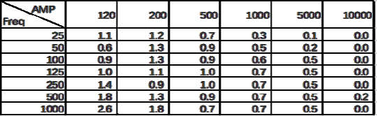
Note: the unit of AMP is a.u., the unit of frequency is Hz, and the unit of distance standard deviation is cm.
2.5 Distance Measurement Characteristics With optimization of light path and algorithm, TFmini Plus has minimized influence from external environment on distance measurement performance. Despite that, the range of distance measurement may still be affected by the environment illumination intensity and the reflectivity of detection object. As shown in Figure 2:
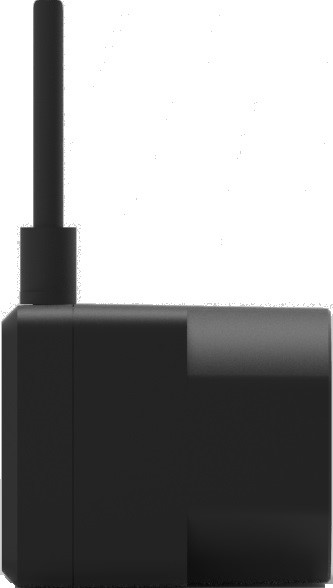
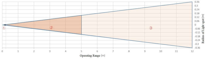
Figure 2 Schematics of Range of distance measurement and Effectiveness of the Product
1 Represents the detection blind zone of TFmini Plus, 0-10cm, within which the output data is unreliable. 2 Represents the operating range of TFmini Plus detecting black target with 10% reflectivity, 0.1-4m. 3 Represents the operating range of TFmini Plus detecting white target with 90% reflectivity, 0.1-12m. Vertical Coordinates: Represents the radius of light spot for TFmini Plus at the different distances. The diameter of light spot depends on the FOV of TFmini Plus (the term of FOV generally refers to the smaller value between the receiving angle and the transmitting angle), which is calculated as follows:
DESCRIPTION
d = D ∙ tan β
In the formula above, d is the diameter of light spot; D is detecting range; β is the the value of the receiving angle of TFmini Plus, 3.6°. Correspondence between the diameter of light spot and detecting range is given in Table 3. Table 3 the Minimum side length of effective detection corresponding to Detecting Range Detecti ng 1m 2m 3m 4m 5m 6m 7m 8m 9m 10m 11m 12m range Minim um 6cm 12c 18c 24c 30c 36c 42c 48c 54c 60c 66c 72c side m m m m m m m m m m m length If the light spot reaches two objects with different distances, as shown in Figure 3, the output distance value will be a value between the actual distance values of the two objects. For a high accuracy requirement in practice, the above situation should be noticed to avoid the measurement error.
Dist1
Dist Dist2
Dist2 > Dist > Dist1
Figure 3 Distance Measurement in the case of Two Objects of Different Distances
APPEARANCE AND STRUCTURE
3 APPEARANCE AND STRUCTURE
3.1 Product Structure
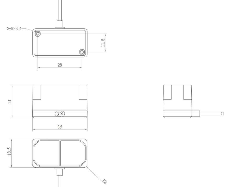
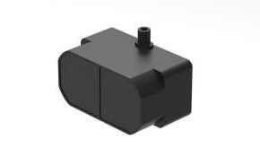
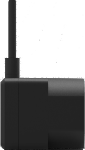
Figure 4: Constructional Drawing of TFmini Plus
M2 positioning screw was recommended, and please choose an appropriate length according to installation requirements.
ELECTRICAL CHARACTERISTICS
4 ELECTRICAL CHARACTERISTICS
Table 4: Major Electrical Parameters of TFmini Plus
Description Parameter value Supply voltage 5V±0.5V Average current ≤110mA Peak current 140mA Average power 550mW Communication level LVTTL(3.3V)
This product has no over-voltage nor polarity protection, so please make sure that connection and power supply are normal. The fluctuation of the power supply voltage in a range of ±0.5V is allowable. Average current varies along with the operating modes of the product in two patterns, more specifically, its current is around 50mA under short distance mode and it is around 140mA under long distance mode.
LINE SEQUENCE AND DATA COMMUNICATIOIN PROTOCOL
5 WIRE SEQUENCE AND DATA
COMMUNICATION PROTOCOL
5.1 Description about Line Sequence and
Connection
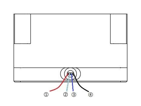
PIN-1 PIN-4
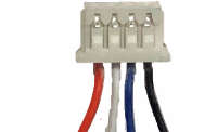
Table5: The Function and Connection Description of each pin
No. Color Corresponding PIN Funciton Comment ① Red PIN-1 +5V Power supply ② White PIN-2 RXD/SDA Receiving/Data ③ Green PIN-3 TXD/SCL Transmitting/Clock ④ Black PIN-4 GND Ground
TFmini Plus has a 30cm long connecting wire with a JST 1.25-4P (Molex51021-0400) connector. The connecting wire can be extended as needs. To ensure effective data transmission, the length of connecting wire should be short than 1m. 5.2 Serial port Communication Protocol TFmini Plus adopts the serial port data communication protocol, as given in Table 6. Table 6 Data Communication Protocol of TFmini Plus
Communication interface UART Default baud rate 115200
Data bit 8 Stop bit 1
LINE SEQUENCE AND DATA COMMUNICATIOIN PROTOCOL
Parity check None
5.3 Data Output Format of Serial port TFmini Plus is available with two formats of data output, namely, the standard data output format and the character string data format, both of which are switchable with command. Standard data output format (default): Data structure: each data frame contains 9 bytes, including the distance value, signal strength, temperature of chip and data check byte (Checksum), etc. Data format is hexadecimal (HEX). Data codes are detailed in Table 7 Table 7 Data Format and Code Explanation Byte0 -1 Byte2 Byte3 Byte4 Byte5 Byte6 Byte7 Byte8 0x59 59 Dist_L Dist_H Strength Strength Temp_L Temp_H Checksu
_L _H m
Data code explanation
| Parameter | Value |
|---|---|
| Byte0 | 0x59, frame header, same for each frame |
| Byte1 | 0x59, frame header, same for each frame |
| Byte2 | Dist_L distance value low 8 bits |
| Byte3 | Dist_H distance value high 8 bits |
| Byte4 | Strength_L low 8 bits |
| Byte5 | Strength_H high 8 bits |
| Byte6 | Temp_L low 8 bits |
| Byte7 | Temp_H high 8 bits |
Byte8 Checksum is the lower 8 bits of the cumulative sum of the numbers of the
first 8 bytes.
Character string data format The data output is in the format of character string and its unit is m(meter). For example, if the measurement distance is 1.21m, the string 1.21 will be output, followed by the escape character \r\n. 5.4 Descriptions of default Output Data Dist(Distance): Represents the output of the distance value detected by TFmini Plus, with the unit in cm by default. This value is interpreted into the decimal value in the range of 0-1200. When the signal strength is lower than 100 or equal to 65535 (overexposed), the detection is unreliable, TFmini Plus will set distance value to 0. Strength : Represents the signal strength with the default value in the range of
LINE SEQUENCE AND DATA COMMUNICATIOIN PROTOCOL
0-65535. After the distance mode is set, the longer the measurement distance is, the lower the signal strength will be; the lower the reflectivity is, the lower the signal strength will be. When the signal strength is lower than 100 or equal to 65535, the detection is unreliable, TFmini Plus will set distance value to 0. Temp(Temperature): Represents the chip temperature of TFmini Plus. Degree centigrade = Temp / 8 -256
5.5 I²C data communication Table 8 TFmini Plus data communication protocol——I²C
Interface I²C Max transmission rate 400kbps Master/slave mode Slave mode Default address 0x10 Address range 0x01~0x7F
5.6 Timing sequence description of I²C
mode
Different from the serial mode, the I 2 C communication is initiated by the master. TFmini Plus as the slave, can only send and receive data passively. After the sending the config-frame from the master to the slave, one needs to wait for a period for the command to be processed. Then continue the reading procedure. The suggested waiting period is 100ms. To ensure the instantaneity of the measured distance, there is no need to set up the waiting period when sending the ‘obtain measuring result’ frame. Once the command frame is sent by the master, the measured distance can be obtained immediately. Table 9 Timing sequence of the I2C mode St art Ad dr W A Byte 0 A - - Byte N A St op Wait 100ms St art Ad dr R A Byte 0 A - - Byte N A St op
- -
5.7 I/O mode description I/O output mode is supported and could be enabled by related command. See detail
LINE SEQUENCE AND DATA COMMUNICATIOIN PROTOCOL
in chapter 7.4.Command open mode(Mode),critical distance(Dist) and hysteresis zone(Zone) could be configurable: Mode: 0(data output mode),1(I/O mode, low level near and high level far);default value is 0. Dist: critical value, near end value in hysteresis zone, unit is cm, default number is 0. Zone: hysteresis zone range, unit is cm; default value is 0(there is no hysteresis zone). The hysteresis zone could be set by this command, when output is near zone level, output will be switched to far zone level if measured result is higher than far end point; when output is far zone level, output is switched to near zone level if measured result is lower than near end point.(high level:3.3V,low level:0V) Note : Before using I/O mode, please modify the “Distance under threshold” to 1200(By sending command: 5A 07 22 0A B0 04 00 5A 04 11 6F), the problem of wrong alarm at long distance can be avoided.
QUICK TEST
6 QUICK TEST
6.1 Required Tools of Product Test
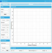
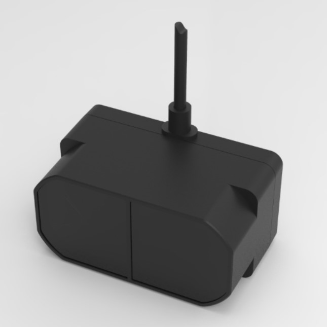
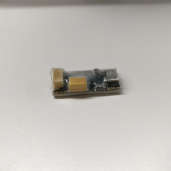
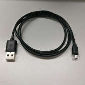
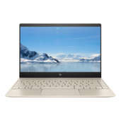
TFmini Plus TTL - USB USB cable PC Test
converter software
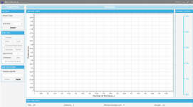
6.2 Test Procedures 1 Download the Test software Please download the Test software of TFmini Plus at our official website (https://ai.benewake.com/en/products/tfmini-plus/). Caution: please shut down any anti-virus software before uncompressing the PC software. Otherwise, maybe the software is deleted as virus. The software is only runnable under Windows environment for the time being. Please refer to Attachment 1 - Product manual of TF Test software.
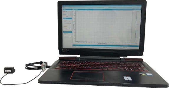
2 Connection of the hardware Connect “TFmini Plus”, “TTL - USB board” and “USB cable” as shown in Figure
6. Make sure there is no loose connection. Then connect “USB cable” with “PC”.
Figure 5 Schematic Diagram of Correct Connection
QUICK TEST
3 Connection to the Test software and data output Open the PC software and select “ ① TFmini Plus” and select automatically recognized occupied serial port (here it is “② COM57”), as shown in Figure 6. Then click “CONNECT”. Upon successful connection, The continuous images of the output data will be displayed in area “④ TIME LINE CHART” on the right. Besides, the real-time data of the Current measure distance (Dist), effective data points per second (Effective Points) and signal strength (Strength) will be displayed in area “⑥ REAL TIME DATA” below.
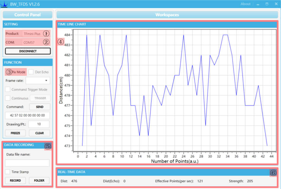
Figure 6 PC software Interface and Display
Notes:
a) If no data is available in area “④ TIME LINE CHART”, please check the line connection and line sequence. When TFmini Plus is successfully powered on, there will be a red indicator light inside transmitting lens viewing from the front. b) If the user want the TFmini Plus output in the Pixhawk format, please select “③Pix Mode” at first, otherwise area “④TIME LINE CHART” will not output the right data image normally. After Pix Mode is checked, the unit of distance will be changed into m automatically. c) The value of distance output Dist may vary with the output unit, which is cm by default. If the unit of distance is changed to the unit-mm with specific command, and the PC software will be unable to identify it, and so the unit
QUICK TEST
of “④TIME LINE CHART” will still be cm. For example, the actual TFmini Plus measurement is 1m, the distance value of TFmini Plus is 1000 in mm, the value read by the PC software also is 1000, but the unit will not change and still display cm.
DESCRIPTIONS ON USER-DEFINED PARAMETER CONFIGURATION
7 DESCRIPTIONS ON USER-DEFINED
PARAMETER CONFIGURATION
7.1 Function Overview The function of user-defined configuration of product parameters is hereby enabled for more flexible settlement of your problems by TFmini Plus. User may modify original parameters by sending relevant commands, such as output data format and frame rate, etc. Please modify product configuration depending upon your actual demands. Do not frequently try irrelevant commands to prevent incorrect sending of command which many cause unnecessary loss. Please make sure to make the configuration as the commands listed herein. Do not send unstated command. 7.2 Command Convention Multi-bytes data or command frame is transmitted in little endian format. For example, decimal number 1000 can be transferred to 0x03E8 in hexadecimal. Then it will be saved in the data or command frame as: 0x5A 0x06 0x03 0xE8 0x03 0x4E 7.3 Command Frame Definition Caution: All configuration commands are sent as hexadecimal digits (HEX). Table 10 Command frame definition Head Len ID Payload Checksum
Remarks
Byte0 Head: frame header(0x5A) Byte1 Len: the total length of the frame(include Head and Checksum,unit:
byte)
Byte2 ID: identifier code of command Byte3-N Data: data segment. Little endian format -2 ByteN-1 Checksum: sum of all bytes from Head to payload. Lower 8 bits
DESCRIPTIONS ON USER-DEFINED PARAMETER CONFIGURATION
7.4 General Parameter Configuration and
Description
Before setting the relevant parameters of TFmini Plus, user needs to establish the connection between TFmini Plus and PC at first. About the connection details, refer to the test connection given in Chapter 6.2. User can send the relevant configuration-related instructions to the product via TFmini Plus PC software or other serial port debugging software. All commands are compatible with both the UART mode and the I 2 C mode. Important: After setting parameters, the ‘Save setting’ command needs to be sent. Table 11 General Parameter Configuration and Description
| Parameter | Value |
|---|---|
| Parameter Command | Response Remark Default |
| s | setting |
| Obtain | 5A 07 01 V1 V2 V3 |
| firmware 5A 04 01 5F | SU Version V3.2.1 |
version
| Parameter | Value |
|---|---|
| System 5A 04 02 60 | ⑤ 5A 05 02 00 61 Succeeded / |
| reset | 5A 05 02 01 62 Failed / |
| Frame rate 5A 06 03 LL HH | 5A 06 03 LL HH SU 1-1000Hz ① 100Hz |
SU
After setting the
Trigger frame rate to 0, detection 5A 04 04 62 Data frame detection can be
triggered with this command
| Parameter | Value |
|---|---|
| 5A 05 05 01 65 | 5A 05 05 01 65 Standard 9 bytes(cm) √ |
| Output 5A 05 05 02 66 | 5A 05 05 02 66 Pixhawk / |
| format | Standard 9 bytes |
| 5A 05 05 06 6A | 5A 05 05 06 6A (mm) / |
Set baud rate ② E.g.
Baud rate 5A 08 06 H1 5A 08 06 H1 H2 256000(DEC)=3E800(115200
H2 H3 H4 SU H3 H4 SU HEX),
H1=00,H2=E8,H3=03,
H4=00
DESCRIPTIONS ON USER-DEFINED PARAMETER CONFIGURATION
Enable/Dis 5A 05 07 00 66 5A 05 07 00 66 Disable data output / able
| Parameter | Value |
|---|---|
| output 5A 05 07 01 67 | 5A 05 07 01 67 Enable data output √ |
| Communic | 0(UART) |
| ation 5A 05 0A | 5A 05 0A 00 69 1(I 2 C) UART |
interface MODE SU setup Modify slave 5A 05 0B ADDR 5A 05 0B ADDR SU Modify 0x10 address of SU I2c_slave_addr I 2 C
| Parameter | Value |
|---|---|
| 5A 05 00 01 60 | Data |
| Obtain | Frame(9bytes-cm |
| Data | ) Only works in IIC / |
| Frame 5A 05 00 06 65 | Date mode |
Frame(9bytes-m
m)
Open or close I/O
output mode
MODE:
| Parameter | Value |
|---|---|
| 5A 09 3B | 0--standard data |
| I/O mode MODE DL DH | mode 0(standard |
| enable ZoneL ZoneH | 1--I/O, near high and data |
| SU | far low mode) |
2--I/O, near low and
far high
Zone: hysteresis
zone
DESCRIPTIONS ON USER-DEFINED PARAMETER CONFIGURATION
E.g. When strength is Strength
| Parameter | Value |
|---|---|
| Strength | below 100, make Threshold= |
| Threshold | distance output 100 |
| and 5A 07 22 XX LL | 5A 07 22 XX LL HH 1200cm. Distance |
| Distance HH 00 | SU XX=100/10=10(DEC)= under |
| under | 0A(HEX) threshold= |
| threshold ③ | 1200(DEC)=4B0(HEX) 0 |
LL=B0,HH=04
Range of X(HEX) is
0~A, frame rate can’t
over 10Hz under low
| Parameter | Value |
|---|---|
| Low power 5A 06 35 0X 00 | power consumption |
| consumpti SU | 5A 06 35 0X 00 SU mode; / |
| on mode | X>0, low power mode |
on;
X=0, low power mode
off ⑥
Restore 5A 05 10 00 6F Succeeded factory 5A 04 10 6E 5A 05 10 01 70 Failed settings Save 5A 04 11 6F ④ 5A 05 11 00 70 Succeeded settings 5A 05 11 01 71 Failed Note: Bytes with yellow undertone represents checksum. 1 The default update rate is 100Hz. The customized update rate should be calculated by the formula: 1000/n (n is positive integer). Increasing frame rate will decrease the data stability. 2 Only standard baud rates are supported. When setting a high update rate, a high baud rate is recommended to ensure data security. After sending baud rate command, keep power on and switch to the target baud rate before sending save setting command, it will be effect in this way. 3 If the threshold is less than 100, the distance will become unstable when the strength is below 100.
DESCRIPTIONS ON USER-DEFINED PARAMETER CONFIGURATION
4 Please always send the command of save settings and wait about 1s when try to modify parameters of TFmini Plus, otherwise the settings will not take effect. 5 Please keep power on and wait 1s after sending system reset command, otherwise the settings will not take effect. 6 After converting low power mode to normal power mode, frame rate will be same as low power mode, if 100Hz is needed, please change the frame rate to 100Hz by command after turning off low power mode.
REMOTE UPGRADING
8 REMOTE UPGRADING
TFmini Plus supports the remote upgrade. When the user’s product cannot satisfy the current application requirements and Benewake official website has relevant firmware upgrades, the user may upgrade the product firmware via remotely upgrading the PC software. Please contact us to get the Updater
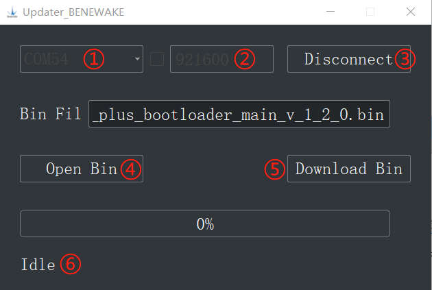
Figure 7 Firmware Upgrade PC software of TFmini Plus
The tools for the firmware upgrade of TFmini Plus are mostly the same as the Quick Test, which requires one TTL-USB board to connect the TFmini Plus with PC. Upon successful connection, open the Updater.exe. Select right port, here is “ ① COM8”. Input the right baud rate in “ ② 115200” and click “ ③ CONNECT” to connect the TFmini Plus with the Updater. Click “ ④ Open Bin” to choose the updating firmware, whose directory will be showed in the textbox above. Then click “⑤ Download Bin” to start upgrading. The information of upgrading will be showed in “⑥”. Caution: please confirm that the communication bit rate of this product is 115200 before the firmware upgrade, as TFmini will be unable to upgrade at other bit rates.
MALFUNCTION:CAUSES AND TROUBLESHOOTING
9 MALFUNCTION: CAUSES AND
TROUBLESHOOTING
(1) Distance value occasionally will abruptly change into 0 beyond the range during normal operation. Cause: The different test environments (reflectivity of detected object, disturbance of ambient light, etc.) will affect the signal strength of TFmini Plus. For a reliable and stable measurement data, the algorithm elimination is internally used for TFmini Plus. In case of the insufficient signal strength, TFmini Plus will output 0. This value is not measurement data of TFmini Plus, which is only used to remind the user that such data is unreliable. Troubleshooting: please use such value as the trigger signal of some unreliable data, and it will ensure that your system can use other reliable data for further assessment and decision-making if there are some unreliable data. (2) Significant error between the output distant value of LiDAR and actual distance Cause ①: Incorrect interpretation of the data communication protocol of TFmini Plus. Troubleshooting: check data communication interpretation means. In case of such error, please check the data format to adjust interpretation means. Cause ② : Due to the physical principles of TFmini Plus, the above phenomenon is likely to occur if the detection object is the material with high reflectivity (such as mirror, smooth floor tile, etc.) or transparent substance (such as glass and water, etc.) Troubleshooting: Please avoid use of this product under such circumstance in practice. Cause ③: The IR-pass filters are blocked. Troubleshooting: please use dry dust-free cloth to gently remove the foreign matter (3) No data output Cause: The product will be strictly inspected before leaving our factory, ensuring that all the shipped products can work normally. However, some abnormal working matters maybe still occur because of incidents during the transportation or use.
MALFUNCTION:CAUSES AND TROUBLESHOOTING
Troubleshooting: Check whether the power supply is normal; check whether the voltage is within rated voltage range. If power supply is normal, there will be a red light inside the transmitting lens of TFmini Plus. Check TFmini Plus with correct connection sequence and reliable connection. Check whether the data interpretation is correct. Please carry out the interpretation as per the data format specified herein. If the problem persists, please contact our technical support. (4) There is no data output when LiDAR is connected to PC software. Cause ①: The PC software only supports the Windows operation system for the time being Troubleshooting: Use the PC supporting Windows operation system. Cause ②: TTL - USB board is poorly connected. Troubleshooting: Check the TTL -USB board with the correct and reliable connection with TFmini Plus and PC. Cause ③: Driver of serial port is not correctly installed. Troubleshooting: Plug and unplug USB cable again. Try to reinstall the driver or directly download and install a driver from the internet. If the PC software still work abnormally, please contact our technical support.
ATTACHMENT 1
10 Q&A
Q1: Is TFmini Plus available with 3.3V or other power supply voltage? A1: Sorry, it is not available for the time being. The Standard power supply of TFmini Plus is 5V±0.5V. If you have any further requirement, please contact our sales person to consult a customization design matter. Q2: TFmini Plus will heat up after operating for a while. Is it broken? A2: This is the normal operating condition of the product. The temperature of the chip and circuit board will slightly up after a continuous operation, which is a normal case. Q3: Can TFmini Plus be connected with Arduino or Raspberry Pi for use? A3: Yes, it can. TFmini Plus adopts serial communication protocol so that it can connect to any control board supporting serial port communication. Q4: Will TFmini Plus affect each other when there are 2 TFmini Plus work together? A4: When they are face the same direction and two light spots overlap, there is no effect on each other, but if the amount is over 2, they will affect each other. When they are face to face, they interfere with each other.
ATTACHMENT 1
ATTACHMENT 1: INTRODUCTION OF TF
SERIES PC SOFTWARE
This PC software only supports the Windows operating system. It is suitable for any products of TF series, but the output of those products is limited to the serial port
communication protocol. Detailed operations are as below.
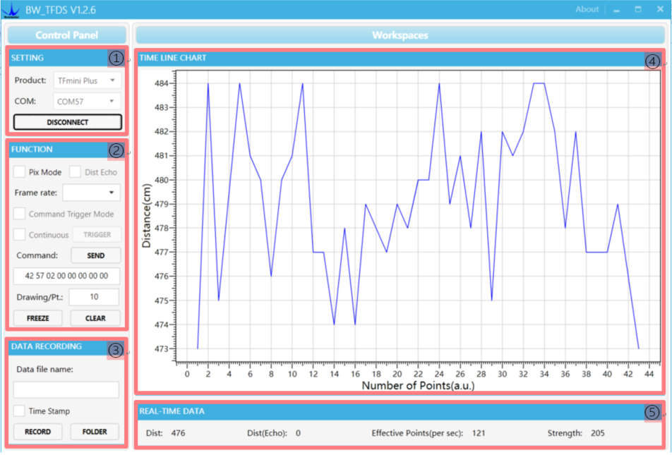
Figure 1: Interface of TF Series PC software
1 Product Type/Serial Port Control Zone [SETTINGS] Product Type: connect the LiDAR via TTL-USB board to the PC. As shown in the figure, select ‘TFmini Plus’. Serial port (COM): select the right serial port number corresponding to the LiDAR. Baud rate is set to 115200 as default. CONNECT/DISCONNECT: Click [CONNECT] button to establish the connection with LiDAR. Click [DISCONNECT] button to terminate the connection. 2 Function Zone [FUNCTION] Pix Mode: check the checkbox to enable Pix mode. Uncheck the checkbox will set
ATTACHMENT 1
TFmini Plus to default output format. In Pix mode, the frame rate (Effective Points) calculated by test software is unreliable. FREEZE/CLEAR: After clicking [FREEZE], time-line chart in zone [4] will stop updating. On clicking [CLEAR], the plotted curve in [4] will be cleared. Frame Rate: choose frame rate from the drop box, setting will be made immediately. Drawing/Pt: upon receipt of every N frames, the PC software will draw one point on the chart [4] the average of the N data. N can be modified depending upon the actual requirement (the value is preferable to be ≥10 to prevent the PC software from lagging). After entering the value, press “Enter” key on the keyboard to enable the setting. Command: Input the commands in hexadecimal format in the text box and click the [SEND] button above to send the command. 3 Data Recording Zone [DATA RECORDING] Input the name of data file in the textbox. Press [RECORD] button to start recording data and click the [FINISHED] button to stop recording. Click [FOLDER] button to open the folder where the data file is saved. Note: when the frame rate of LiDAR is too high, like 1000Hz, the time stamp will be asymmetric due to the massive data stream. 4 Time Line Chart Zone [TIME LINE CHART] The PC software will draw the continuous distance measurement curves based on the received data, where y-coordinates represent the current distance data while x-coordinates represent effective data. 5 Real-time Data Display Zone [REAL-TIME DATA] Dist: Distance, cm by default. Dist(Echo): parameter of TF03. With TFmini Plus, the default value is 0. Effective Points (per sec): indicates effective points refreshed by TF per second (equals to frame rate). Strength (Signal strength): in pix mode, TFmini Plus will not output strength value, so the Strength is 0 by default. 6 Operating Environment and Precautions Operating Environment: this software can only run on Windows system, Win7 and
ATTACHMENT 1
above. The .Net Framework 4.5.2 is needed to use this software. Precautions: Please do not directly connect the product with frame rate more than 500Hz to test software, which will make the UI unresponsive.