
Technical documents
Benewake LiDAR GUI Viewer User Manual
Benewake LiDAR Viewer

Benewake LiDAR Viewer
GUI User Manual
Contents
1 Brief Introduction....................................................................1 1.1 Objective...................................................................... 1
| Parameter | Value |
|---|---|
| 1.2 System Intr oduction | .......................................................... 1 |
| 1.3 Terms and Abbreviations | .................................................... 1 |
| 1.4 Precautions before use | ...................................................... 2 |
2 File Structure........................................................................ 4
| Parameter | Value |
|---|---|
| 3 Interface Introduction | .............................................................. 5 |
| 4 Functions Introduction | .............................................................. 7 |
| 4.1 Point Cloud Display Adjustment | .............................................7 |
| 4.1 .1 Point cloud display | .................................................... 7 |
| 4.1 .2 Point Cloud Display Adjustments | .................................... 9 |
| 4.2 Record and Playback Point Cloud Data | .................................. 12 |
| 4.2. 1 Recording & Playback *. PCD file | .................................... 1 2 |
| 4.2. 2 Recording & Playback *.PCAP file | .................................. 1 3 |
| 4.2. 3 Save *.CSV file | ....................................................... 1 5 |
| 4.3 Functions Related to Device Management Bar | ........................... 1 6 |
| 4.4 To olbar Related Functions | ................................................. 17 |
| 4.4 .1 Scale Display | ........................................................ 17 |
| 4.4 .2 Hue Indicator | ........................................................ 17 |
| 4.4 .3 Distance Measurement | ..............................................18 |
| 4.4 .4 Point Cloud Frame Selection | ....................................... 1 9 |
| 4.4 .5 Per spective Projection | .............................................. 2 0 |
| 4.4 .6 Orthographic Proj ection | ............................................ 2 0 |
| 4.4 .7 Rotation Function | ................................................... 2 1 |
| 4.5 Menu Bar Related Functions | ............................................... 21 |
4.5. 1 File.................................................................... 2 1
| Parameter | Value |
|---|---|
| 4.5. 2 Window | ...............................................................22 |
| 4.5. 3 Device Info rmation | .................................................. 2 2 |
| 4.5. 4 Configuring Device | .................................................. 2 3 |
| 4.5. 5 Point Cloud Display | ................................................. 24 |
| 4.5. 6 Help Menu | ............................................................2 5 |
1 Brief Introduction
1.1 Objective
The purpose of this article is to explain the basic functions, operation methods and precautions of Benewake LiDAR Viewer GUI (hereinafter referred to as BLV ). 1.2 System Introduction
BLV is a GUI software used by AD2 LiDAR , which is mainly used for real- time display, recording and playback of point cloud data. BLV is compiled on the Windows 10 platform, and it is recommended to install and use it on Windows 10 and above systems.
1.3 Terms and Abbreviations
| Parameter | Value |
|---|---|
| Terms abbreviations and | Meaning |
| IP | The IP address of the network protocol used by the LiDAR communication |
| MDOP | Primary data transfer port |
| DCSP | Device control command transmission port |
| DSOP | The port where the device status information is transmitted |
| *.pcd | A file format in which the GUI saves point cloud data, which can be directly read and played back |
by the GUI
*.csv The GUI saves a file with this format for point cloud data, which can be viewed directly in Excel or Word *.pcap A file format in which the GUI saves point cloud data, which can be directly read and played back
by the GUI.
Table . 1: Terms and abbreviations
© 202 4 Be n ew ak e (B e i ji n g) Co., Ltd. · Al l ri gh t s re se r ve d · RE V: 2 4/03 /20 2 4
1.4 Precautions before use
1. Before using the LiDAR , you need to change the IP address of your computer. Network and Internet → Ethernet → Change adapter options → Properties → Internet Protocol version 4 (TCP/IPv4), set the host IP address to remain on the same network segment as the LiDAR IP address (i.e., segment 0), subnet mask 255.255.255.0, and host IP address used in this instruction manual is 192.168.0.10 (the last byte is different from the IP address of the connected device).
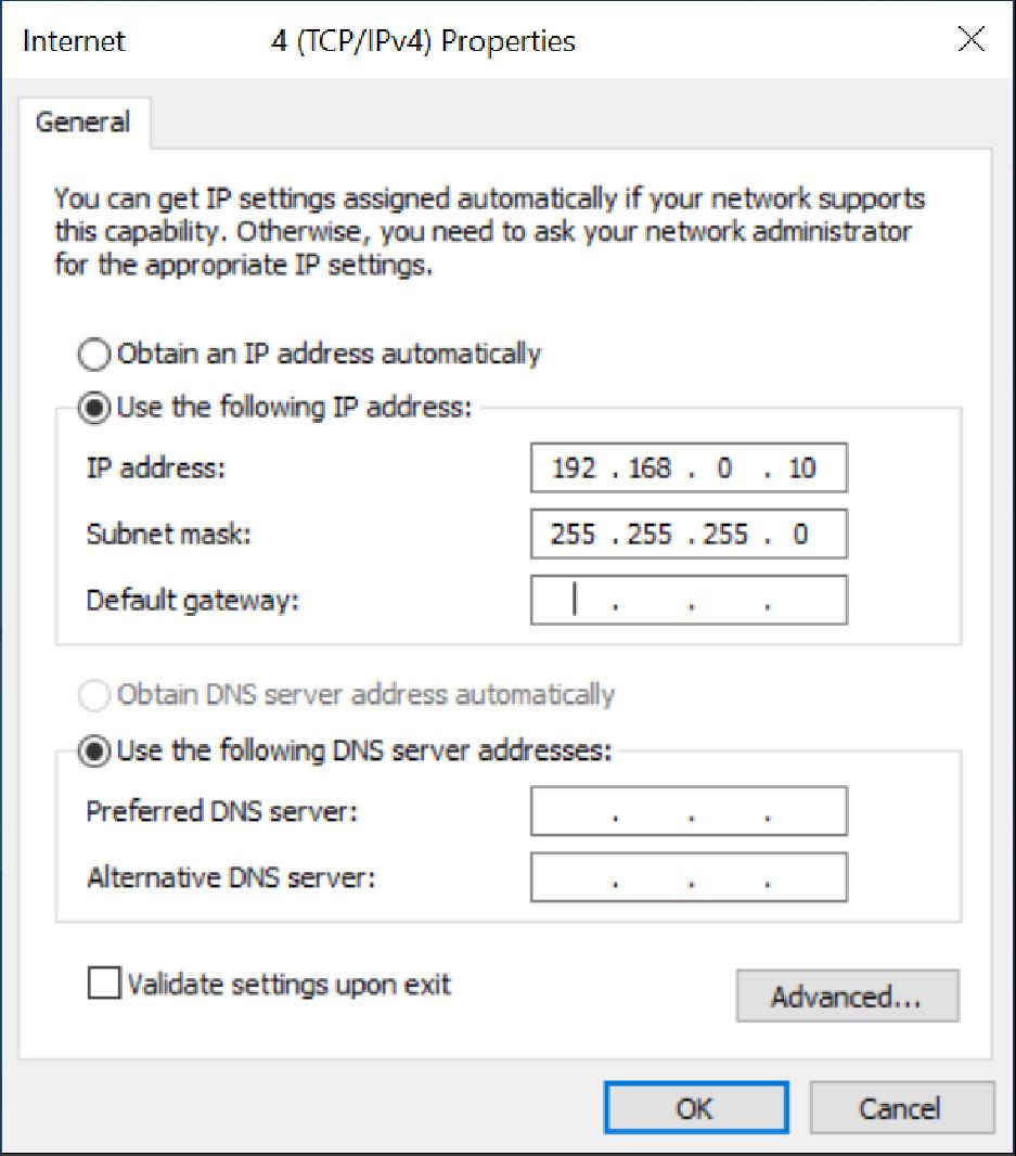
Figure. 1: Configuring IP address
1. Make sure that your computer's firewall is turned off (this is optional: if you can't connect properly, try this step again). Control Panel → System and Security → Windows Defender → Turn on/off Windows Defender Firewall.
© 202 4 Be n ew ak e (B e i ji n g) Co., Ltd. · Al l ri gh t s re se r ve d · RE V: 2 4/03 /20 2 4
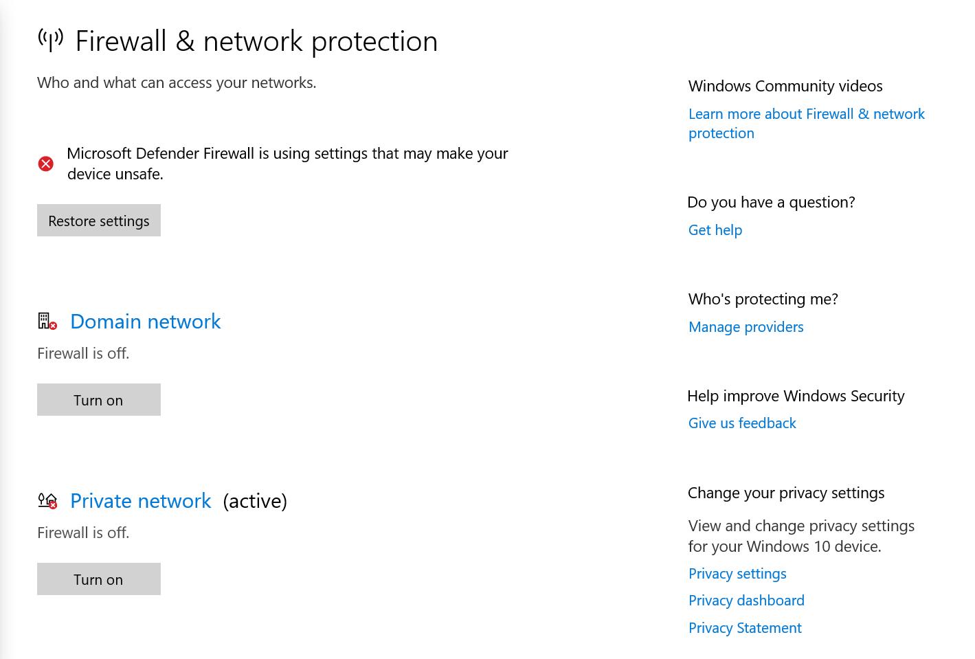
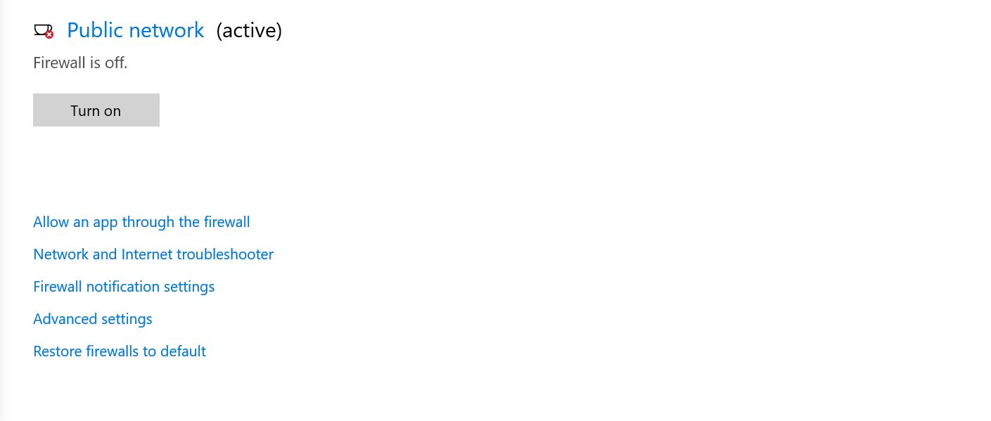
Figure. 2: Turning off firewall
© 202 4 Be n ew ak e (B e i ji n g) Co., Ltd. · Al l ri gh t s re se r ve d · RE V: 2 4/03 /20 2 4
2 File Structure
BLV file structure (part of the file) as shown in the figure, double-click Benewake_ LiDAR _Viewer.exe to open the GUI program.
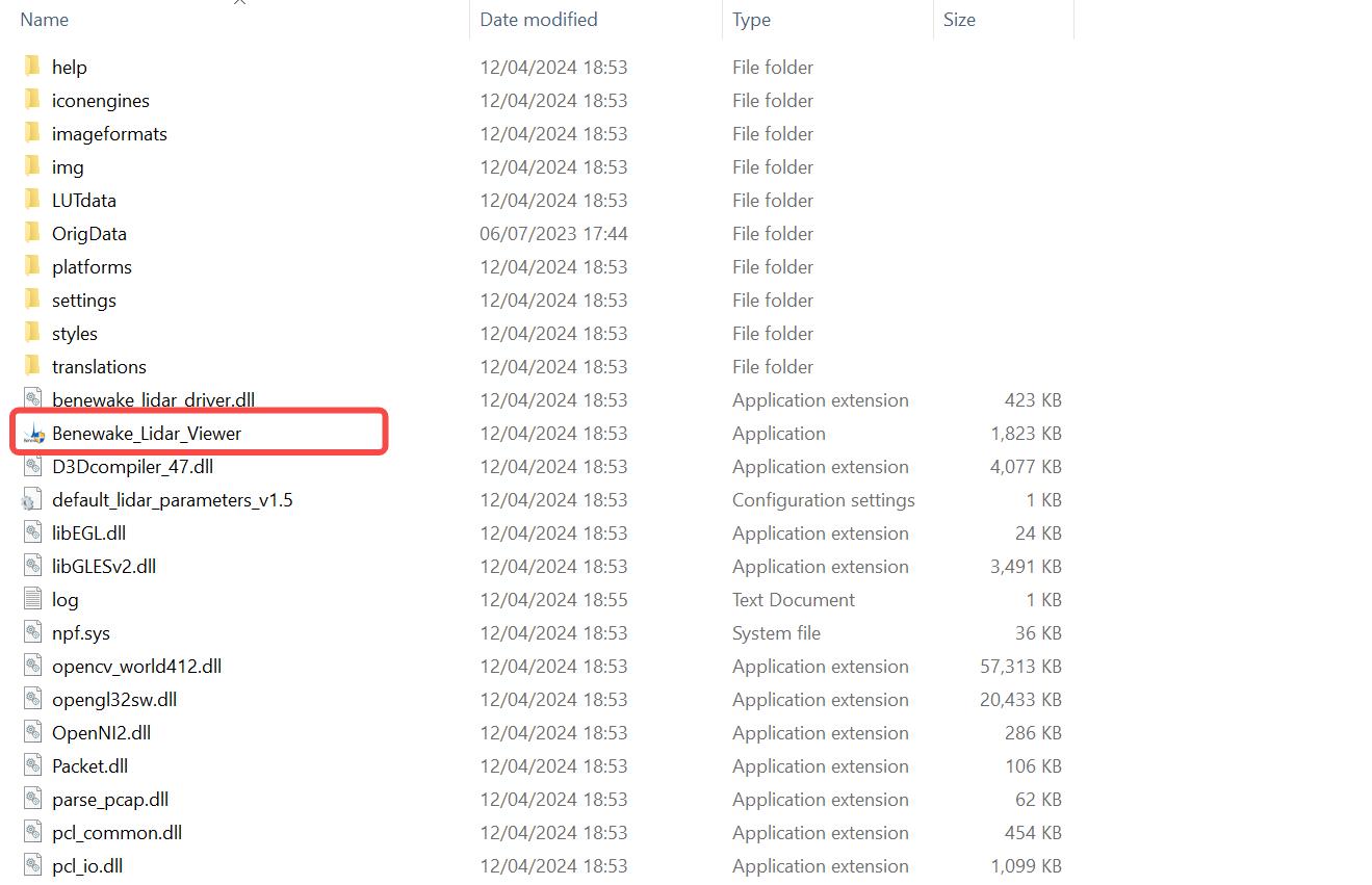
Figure. 3: Screenshot of file structure
© 202 4 Be n ew ak e (B e i ji n g) Co., Ltd. · Al l ri gh t s re se r ve d · RE V: 2 4/03 /20 2 4
3 Interface Introduction
The main interface of BLV is shown in the following figure:
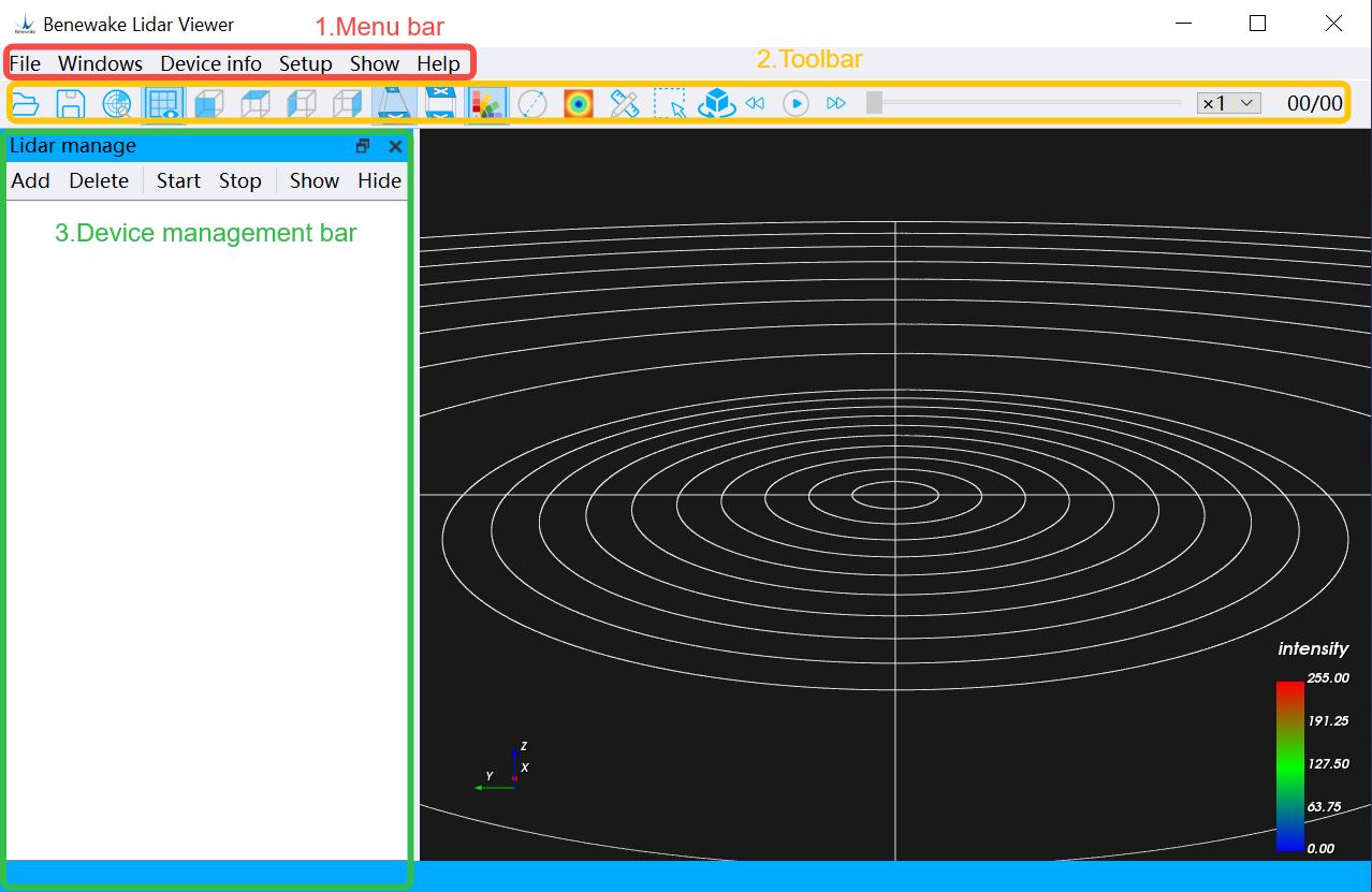
Figure. 4: Benewake LiDAR Viewer main interface
1. Menu Bar: Basic configuration options
2. Toolbar: Basic function options, the specific functions are as follows:
| Parameter | Value |
|---|---|
| Icon Function | Icon Function |
| Playback file | *. PCD Ortho Projection |
| Save*. (from LiDAR ). | PCD file Display the hue indicator map |
| Search for devices in | the current Set the point size |
network
| Parameter | Value |
|---|---|
| Display the scale | Ranging |
| Front view | Box selection |
| Top view | Roaming rotation |
| Left view | Play |
| Right view | Time out |
Perspective projection
Table. 2: Toolbar icons
3. Device Management Bar: Manage device addition and deletion,
© 202 4 Be n ew ak e (B e i ji n g) Co., Ltd. · Al l ri gh t s re se r ve d · RE V: 2 4/03 /20 2 4
control device start and stop, display device information and connection status, etc.
4. Point cloud display area: Displays real-time point clouds or plays point cloud data files.
© 202 4 Be n ew ak e (B e i ji n g) Co., Ltd. · Al l ri gh t s re se r ve d · RE V: 2 4/03 /20 2 4
4 Functions Introduction
4.1 Point Cloud Display Adjustment
4.1.1 Point cloud display
1. Please complete the configuration before use according to Chapter 1.4.
2. Open the BLV software, there are two ways to add LiDAR: [Method 1] (1) Click Device Management Bar → Add button to set the IP, PORT, DSOP of the LiDAR .
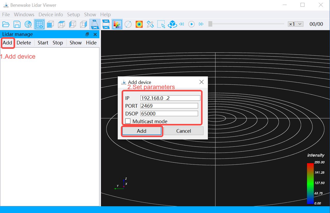
Figure. 5: Add device information
In general, the following table describes the parameters:
Parameter items Parameter value
IP 192.168.0.2
| Parameter | Value |
|---|---|
| PORT | 2469 |
| DSOP | 62702 |
| Multicast mode | Unchecked |
Table. 3: Parameters for adding LiDAR
(3) Finally, confirm the addition. [Method 2] (port is 62702), as shown in the figure, and click OK to complete the 1) Click the icon in the toolbar to search for the device (the search addition.
© 202 4 Be n ew ak e (B e i ji n g) Co., Ltd. · Al l ri gh t s re se r ve d · RE V: 2 4/03 /20 2 4
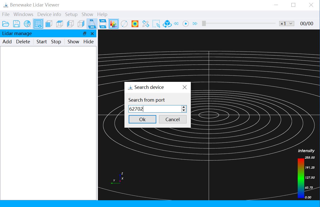
Figure. 6: Searching for a device
(displayed in the Device Management Bar , as shown in the following 2) After the addition is completed, the device information will be figure: (Due to different devices, the device information is not exactly the same, and the device information in the figure is for reference only).
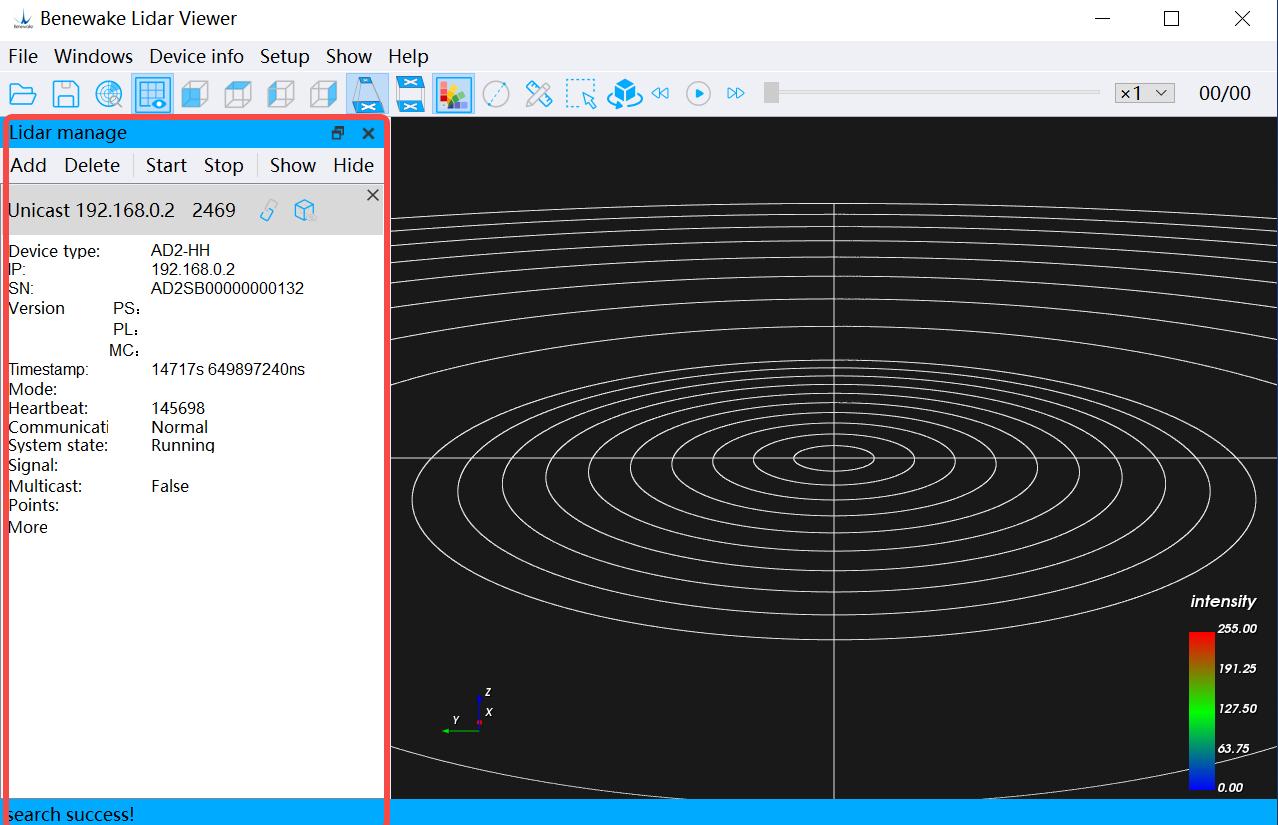
Figure. 7: Adding the device
Starting LiDAR After completing the steps of adding the device, you can click the Device Management Bar → Start button, wait for a while, and then start to get the point cloud data, which will be displayed in the Point Cloud
© 202 4 Be n ew ak e (B e i ji n g) Co., Ltd. · Al l ri gh t s re se r ve d · RE V: 2 4/03 /20 2 4
Display Area in real time. Click the Stop button to stop the LiDAR from working.
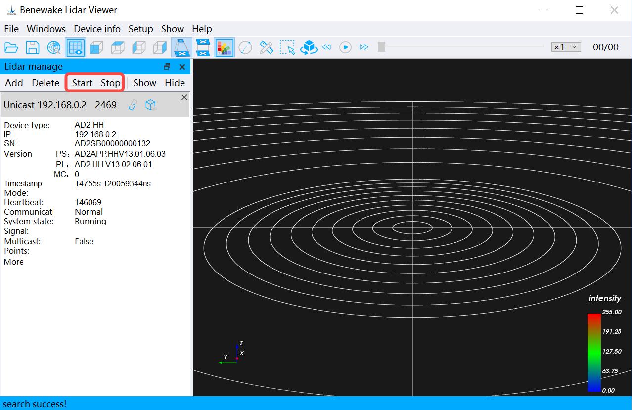
Figure. 8: Device start/shut down buttons
4.1.2 Point Cloud Display Adjustments
1. Point cloud display adjustment: as shown in the red box, the area encircled
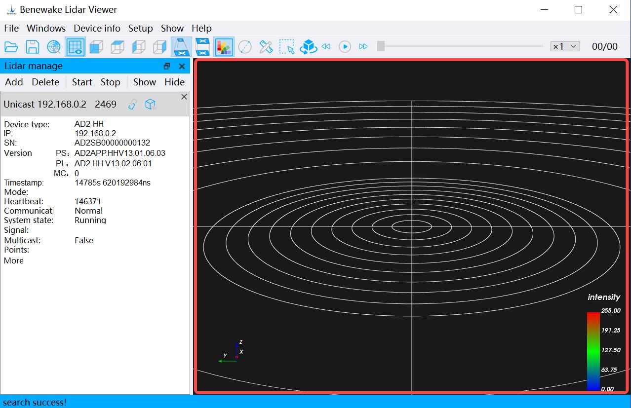
Figure.9: Point cloud display area
The following table describes how to do this: Adjustment results: How to do it: Change the viewing angle of the Hold down the left mouse button
© 202 4 Be n ew ak e (B e i ji n g) Co., Ltd. · Al l ri gh t s re se r ve d · RE V: 2 4/03 /20 2 4
| Parameter | Value |
|---|---|
| point cloud display | and drag in different directions |
| Zoom in/out of the point cloud display | Slide the mouse wheel |
| Move the point cloud display as a whole | Hold (middle down button) the and mouse drag wheel in |
different directions .
Table . 4: Point cloud display adjustment method
Note: When you cannot continue to zoom in on the point cloud display using the mouse wheel, you can continue to zoom in on the point cloud display by clicking the F key on the keyboard. At this point, the point cloud display continues to zoom in centered on the mouse-over position:
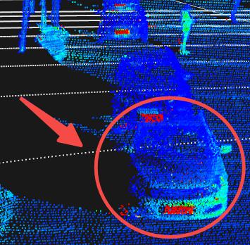
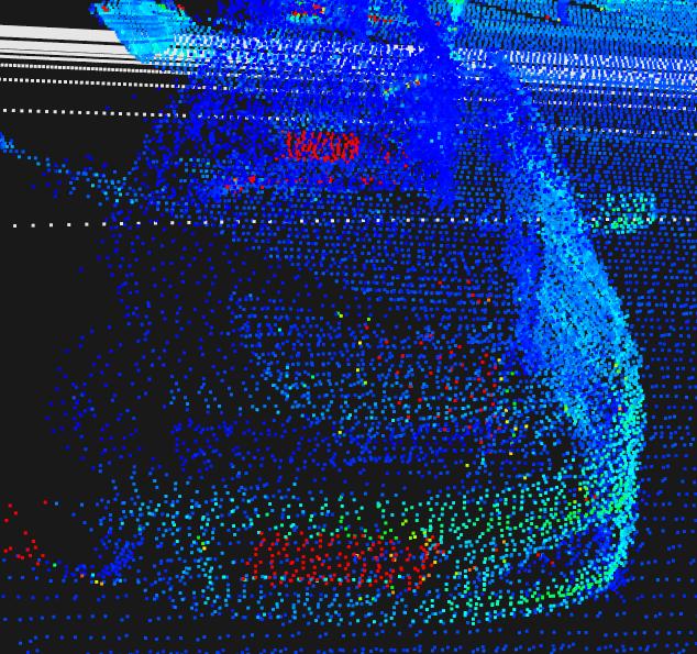
Fi g u re . 10- a: Be for e zoom i n g in wi th F key Fi g u re . 10- b: Afte r zoomi n g in wi th F ke y
2.Angle Adjustment: select the following icons in the Toolbar to adjust the point cloud data display view, or in the Menu Bar → Point Cloud Display → Set View.
Icon Function
Front view Top view Left view Right view
Table. 5: Angle of view adjustment
3.Point Size Adjustment: Click the icon size of the point, and a pop-up window will appear as shown in the in the Toolbar to change the following figure after clicking it (or set it in the Menu Bar → Point Cloud Display → Set Point Size). The point size range is 1~10, and the default setting is 2.
© 202 4 Be n ew ak e (B e i ji n g) Co., Ltd. · Al l ri gh t s re se r ve d · RE V: 2 4/03 /20 2 4
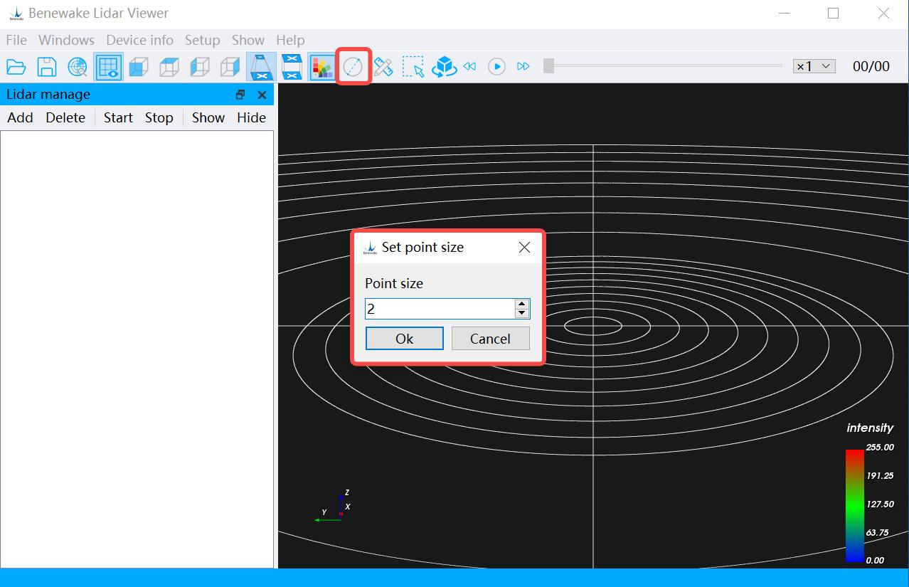
Figure. 11: Setting the point size
4.Set the color scheme: Set the color scheme in the Menu Bar → Point Cloud Display → Set color scheme to render point cloud display according to reflectivity, distance, and elevation (In general, the default rendering color is to render at reflectivity).
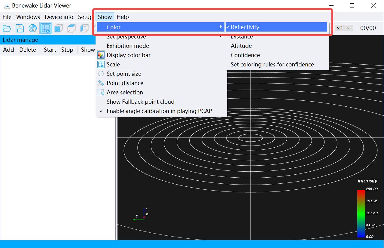
Figure. 12: Setting color scheme
© 202 4 Be n ew ak e (B e i ji n g) Co., Ltd. · Al l ri gh t s re se r ve d · RE V: 2 4/03 /20 2 4
4.2 Record and Playback Point Cloud Data
4.2.1 Recording & Playback *.PCD file
1. Click the Menu Bar → File → Save File → Save PCD File (from the device), select the save path to start recording (or click the Toolbar Save File → Stop Saving PCD File (From Device) option to stop the icon). If you need to end the recording, click the Menu Bar → File → recording (or click the Toolbar icon). (Note: You need to choose the storage location, it is recommended to create a new dedicated folder to save *PCD data).
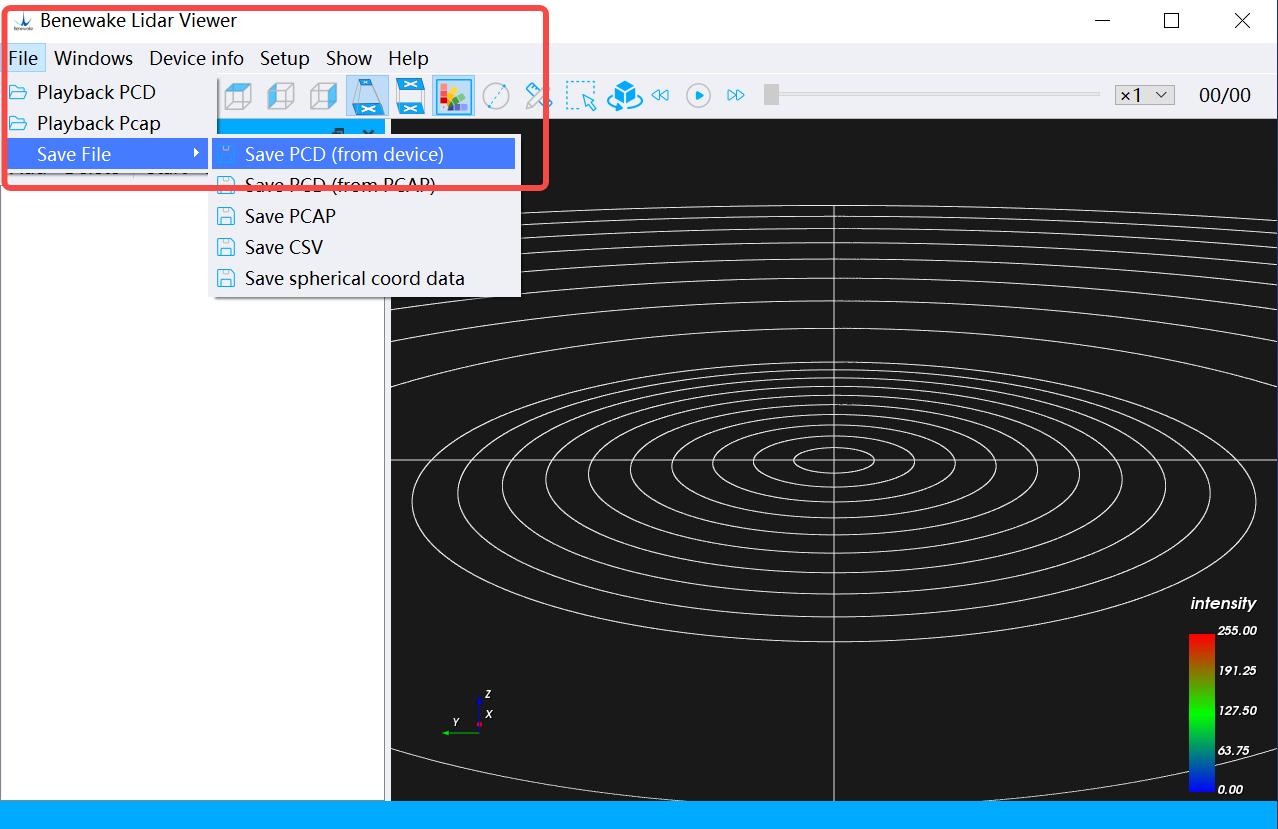
Figure. 13: Recording PCD file
2. After you start recording, you can find the generated *.PCD files under the saved path of the settings, which are the corresponding point cloud data, are named according to the timestamp.
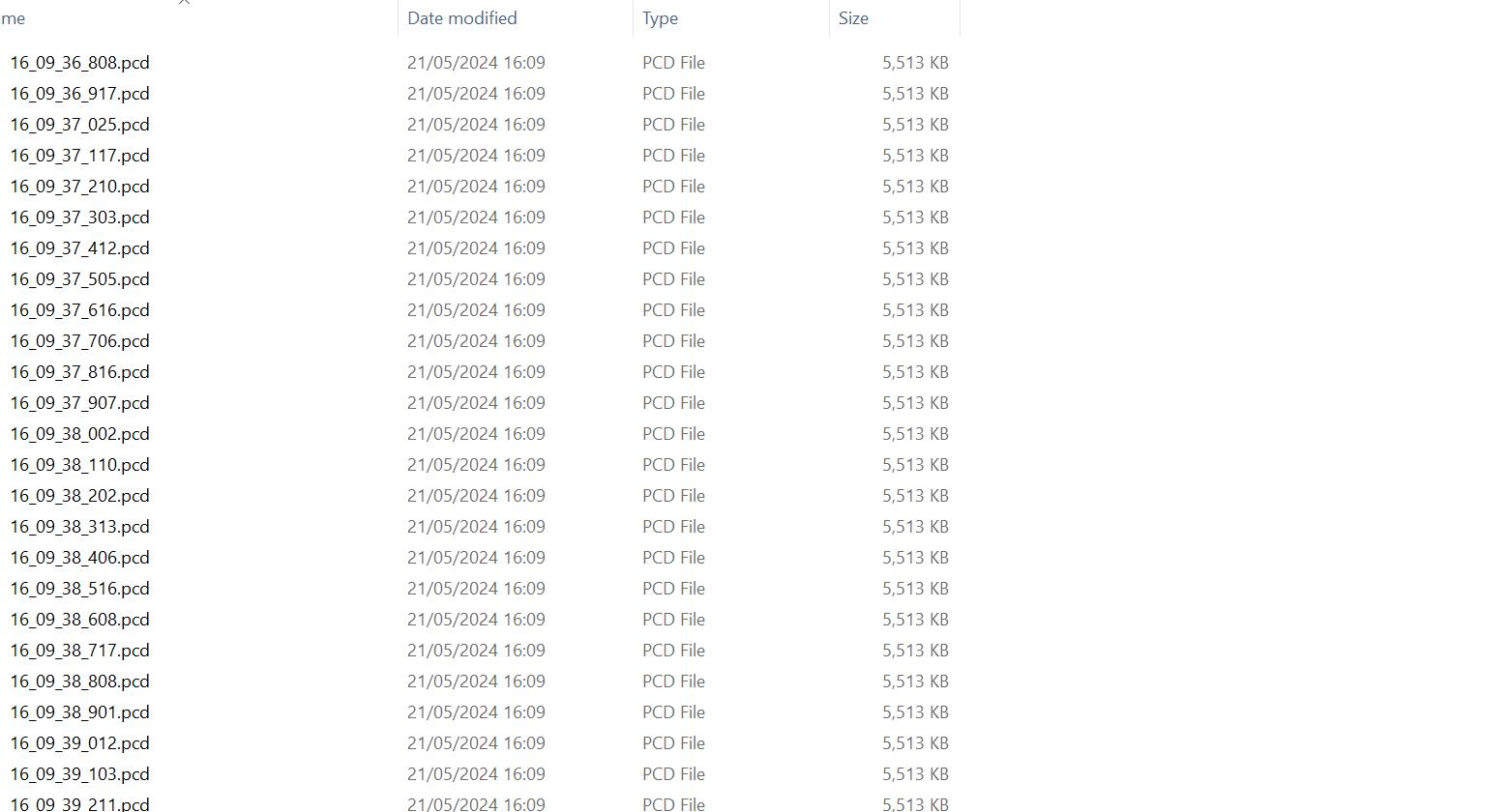
Figure. 14: *.PCD files generated during recording
3. Click the Menu Bar → File → Playback PCD File option (or click the toolbar icon ) to find the saved path you have set after waiting for
© 202 4 Be n ew ak e (B e i ji n g) Co., Ltd. · Al l ri gh t s re se r ve d · RE V: 2 4/03 /20 2 4
a while, click the icon in the toolbar to play back *.PCD files.
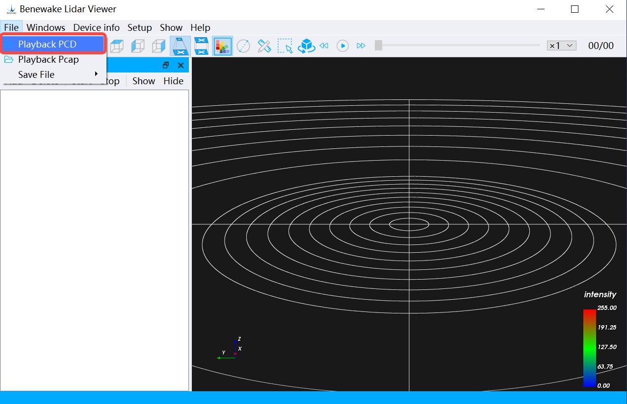
Figure. 15: Playback *. PCD file
4. Once playback starts, the can tap to pause the playback data at any time. You can drag the icon will change to an icon, and you progress bar to view the point cloud data you want to focus on.
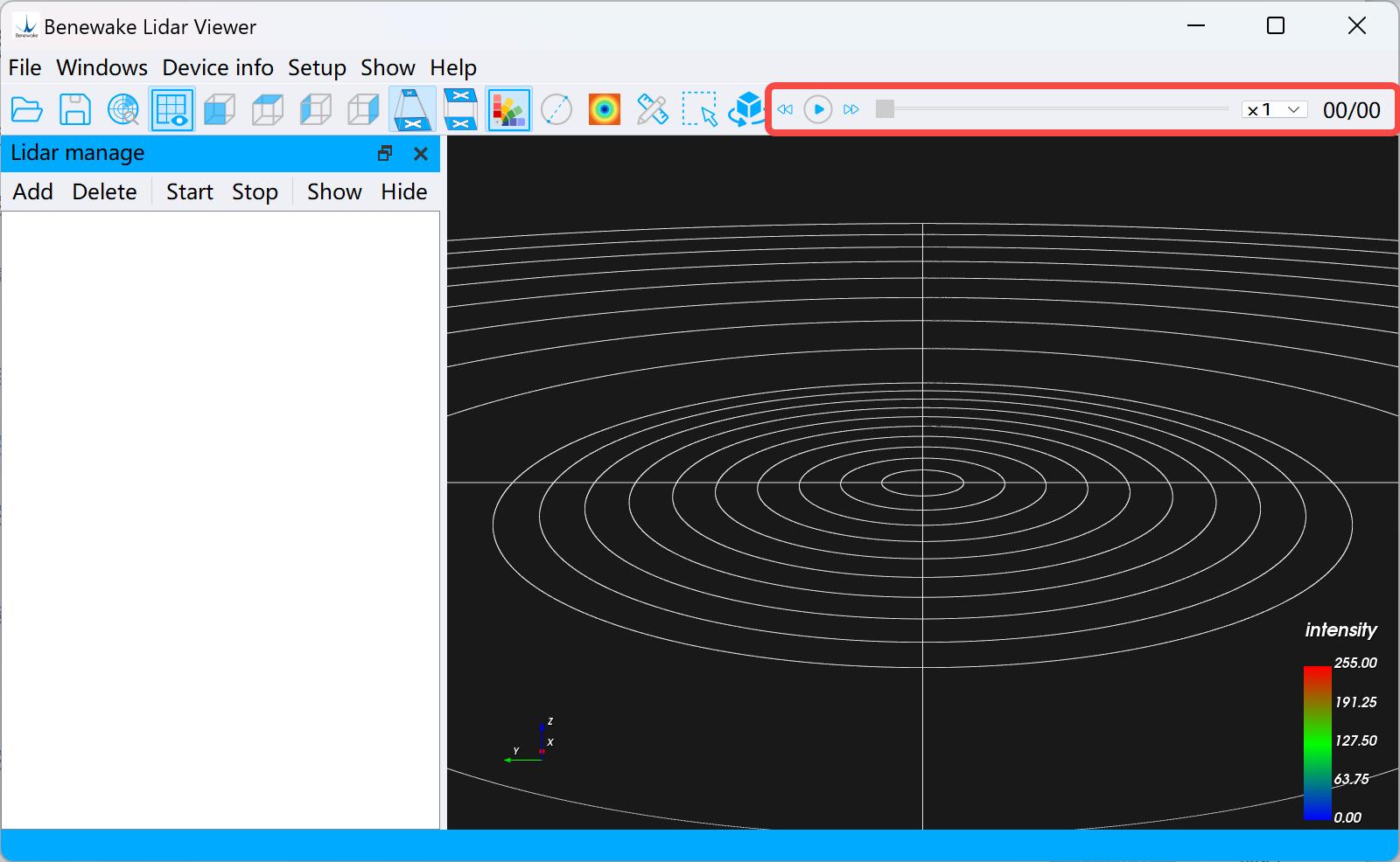
Figure. 16: Point cloud playback control bar
4.2.2 Recording & Playback *.PCAP file
1. Click the Menu Bar → File → Save File → Save PCAP File options, select the save path, set the file name, and start recording. If you
© 202 4 Be n ew ak e (B e i ji n g) Co., Ltd. · Al l ri gh t s re se r ve d · RE V: 2 4/03 /20 2 4
need to end the recording, click the Menu Bar → File → Save File → Stop Saving PCAP File options to stop the recording. If the recording is successfully stopped, a pop-up window will prompt that the saving is successful. (Note: You need to choose the storage location, it is recommended to create a new dedicated folder to save *PCAP data).
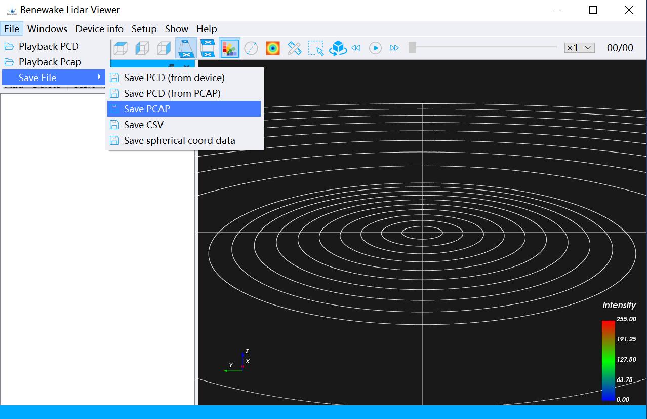
Figure. 17: Save *.PCAP file
2. Click on the Menu Bar → File → Playback PCAP File option, and select Save the finished *.PCAP file, after a while, a pop-up window will prompt that the file has been successfully imported. Click the icon in the toolbar to play back *.PCAP file.
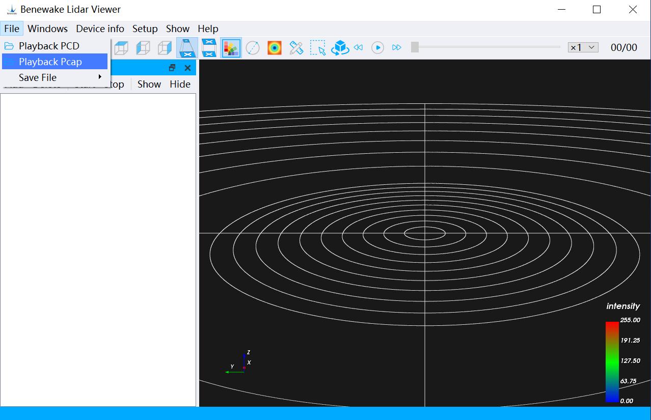
Figure. 18: Playback *.PCAP file
3. Follow-up and playback *. PCD files.
© 202 4 Be n ew ak e (B e i ji n g) Co., Ltd. · Al l ri gh t s re se r ve d · RE V: 2 4/03 /20 2 4
4.2.3 Save *.CSV file
1. Click the Menu Bar → File → Save File → Save CSV File option, and select the save path, you can save a frame of data in the save path, and the recorded file will be named according to the timestamp. Use Excel to open a saved *.CSV file. recommended to create a new dedicated folder to save *. CSV data). (Note: You need to choose the storage location by yourself, it is
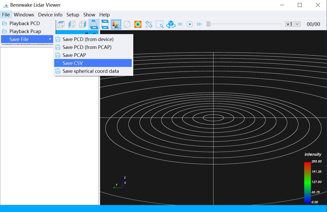
Figure. 19: Save *.CSV file

Figure. 20: Save the finished one*.CSV file
© 202 4 Be n ew ak e (B e i ji n g) Co., Ltd. · Al l ri gh t s re se r ve d · RE V: 2 4/03 /20 2 4
4.3 Functions Related to Device
Management Bar
As shown in the figure below, click the corresponding button in the Device Management Bar to use the corresponding functions.
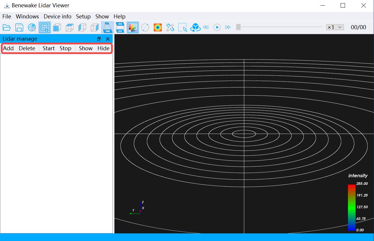
Figure. 21: Optional functions in device management bar
1. Add: Add a new LiDAR device
2. Delete: Delete the added device
3. Start: Run the devices that have been added
4. Stop: Stop the running device that you added
5. Display : Display the point cloud data of the selected device in the point cloud display area
6. Hide: Hide the point cloud data of the selected device
© 202 4 Be n ew ak e (B e i ji n g) Co., Ltd. · Al l ri gh t s re se r ve d · RE V: 2 4/03 /20 2 4
4.4 Toolbar Related Functions
4.4.1 Scale Display Select/invert the icon in the toolbar displayed, and the contrast (comparison) effect is shown in the following to control whether the scale is figure:
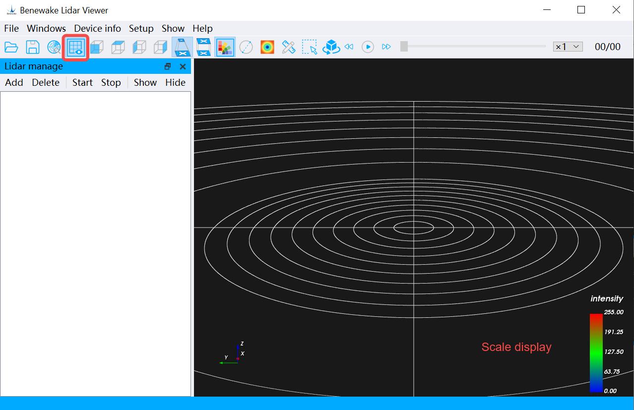
Figure. 22-a: Scale shows contrast (comparison)
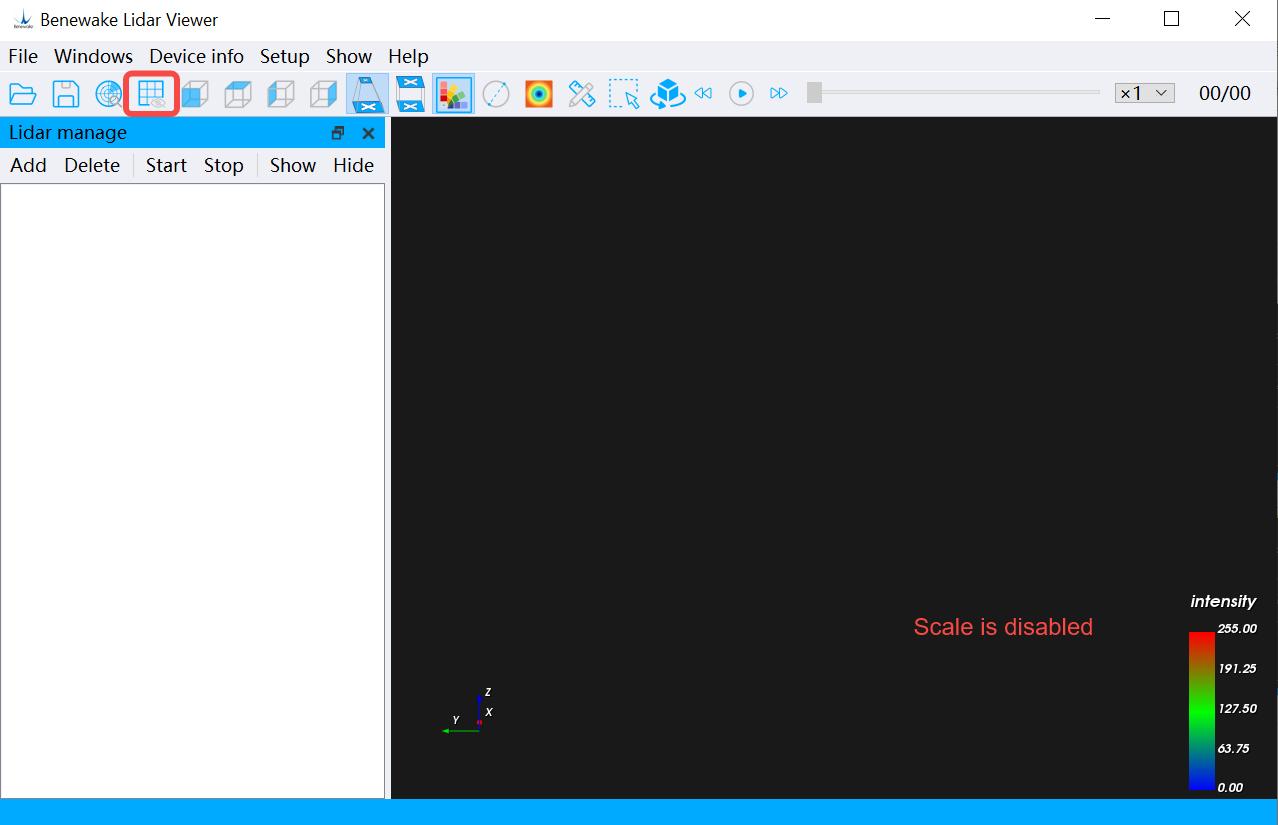
Figure. 22-b: Scale is disabled
4.4.2 Hue Indicator Select/invert the icon in the toolbar indicator bar is displayed, and the contrast effect is shown in the to control whether the hue following figure:
© 202 4 Be n ew ak e (B e i ji n g) Co., Ltd. · Al l ri gh t s re se r ve d · RE V: 2 4/03 /20 2 4
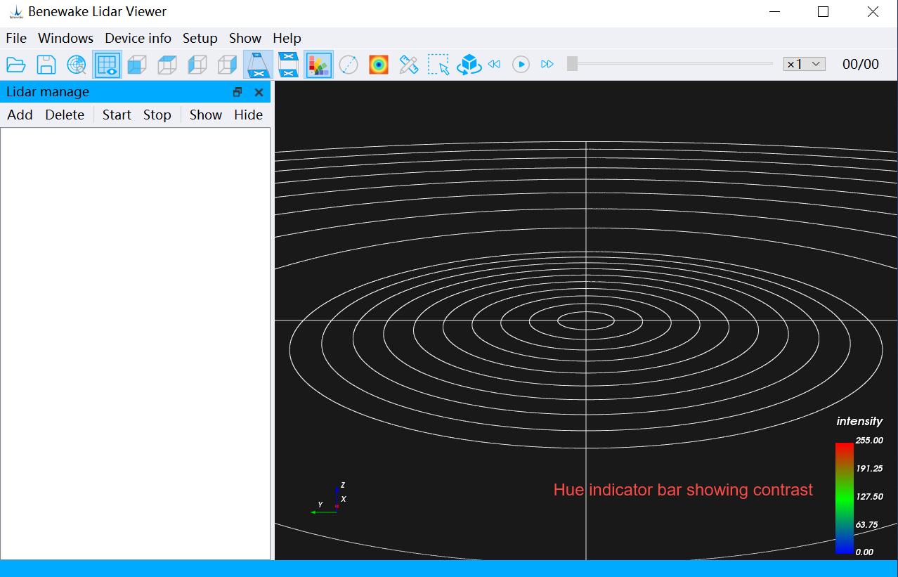
Figure. 23-a: Hue indicator bar showing contrast (comparison)
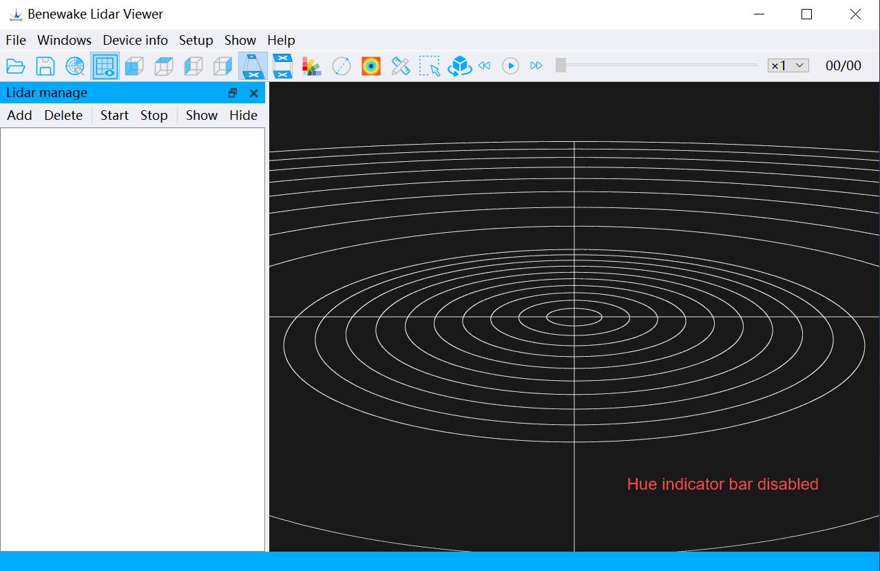
Figure. 23-b: Hue indicator bar disabled
4.4.3 Distance Measurement Click the icon in the toolbar point cloud. Stop the device, click to perform ranging operations on the the icon, use the left mouse button to select the point to be measured on the point cloud data in the point cloud display area, the selected point will be displayed in red, after selecting two points, the distance between the two points can be automatically calculated, and the distance information will be displayed near the ranging line, and the distance measurement function can be turned off by clicking the icon again.
© 202 4 Be n ew ak e (B e i ji n g) Co., Ltd. · Al l ri gh t s re se r ve d · RE V: 2 4/03 /20 2 4
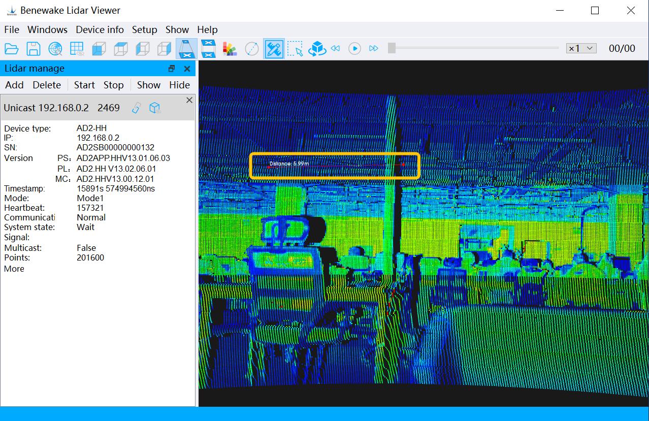
Figure. 24: Point cloud ranging
4.4.4 Point Cloud Frame Selection Click the icon the icon, click the Left Mouse Button once in the Point Cloud Display in the toolbar to select the point cloud. After clicking Area, press the X key on the keyboard, then press and hold the Left Mouse Button to select the point cloud image (can be selected multiple times), and release the Left Mouse Button to complete the box selection. The selected point cloud data is shown in red, and an information window will appear on the right side of the BLV interface to display detailed information of the selected point cloud. Then press the X key on your keyboard and invert the icon to turn off the box selection.
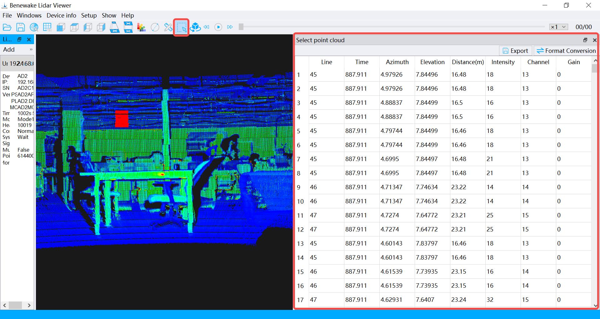
Figure.25: Point cloud box selection
© 202 4 Be n ew ak e (B e i ji n g) Co., Ltd. · Al l ri gh t s re se r ve d · RE V: 2 4/03 /20 2 4
4.4.5 Perspective Projection Depending on your display requirements, select the icon Toolbar to change the display of point cloud data. The point cloud in the display effect of perspective projection is closer to the visual effect of human eye.
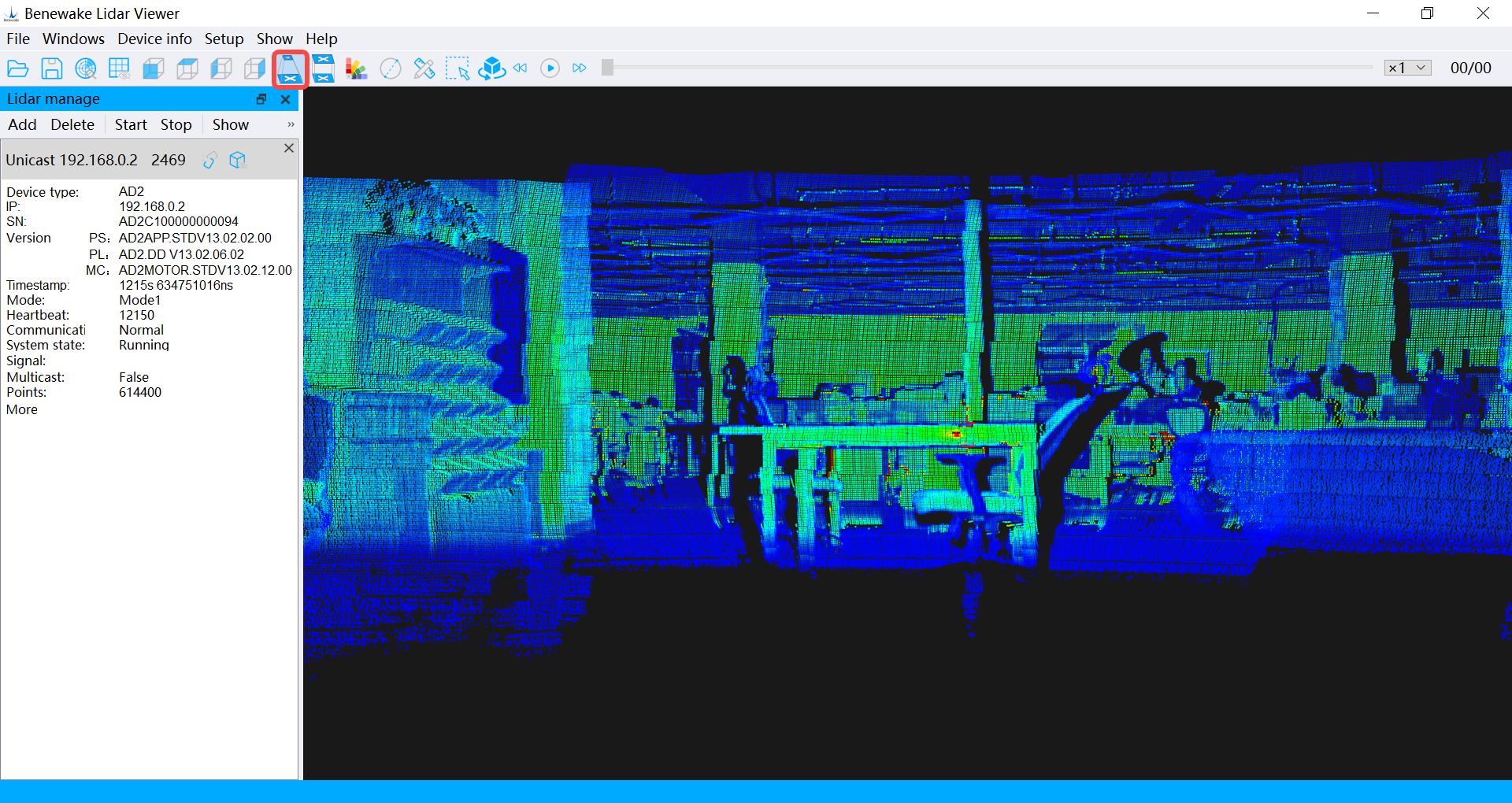
Figure. 26: Perspective projection display effect
4.4.6 Orthographic Projection According to your requirements, click the icon change the display effect of the point cloud data to ortho projection. In in the Toolbar to the ortho projection effect, objects near and far are scaled at the same scale.
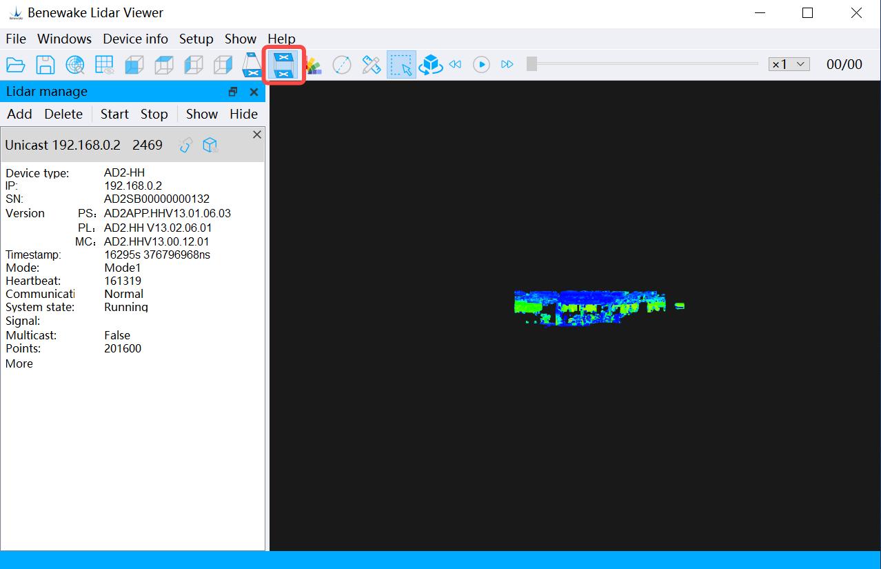
Figure. 27: Orthographic display effect
© 202 4 Be n ew ak e (B e i ji n g) Co., Ltd. · Al l ri gh t s re se r ve d · RE V: 2 4/03 /20 2 4
4.4.7 Rotation Function Click the icon enabled, the point cloud display will rotate slowly 360° horizontally in the toolbar to turn on the rotation function. When along the plane formed by the X-axis and Y-axis of the LiDAR with the Z-axis of LiDAR as the rotation axis.
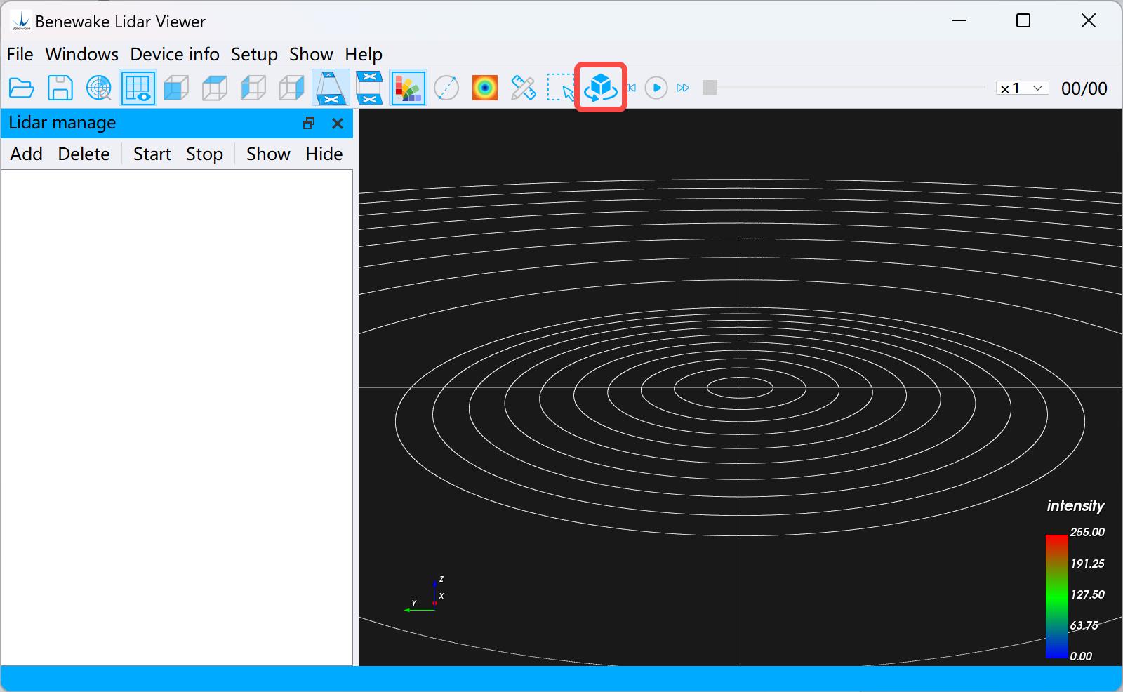
Figure. 28: Rotation function
4.5 Menu Bar Related Functions
4.5.1 File As shown in the figure, file menu main functions are: playback PCD file, play back PCAP file, save PCD file, save CSV file, save the PCAP file, etc. For more information, please see 4.2 Chapter .
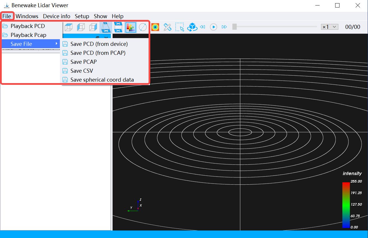
Figure. 29: File menu
© 202 4 Be n ew ak e (B e i ji n g) Co., Ltd. · Al l ri gh t s re se r ve d · RE V: 2 4/03 /20 2 4
4.5.2 Window As shown in the figure, click the Menu Bar → Window → Open/Close Device Window options to display and hide the device management bar.
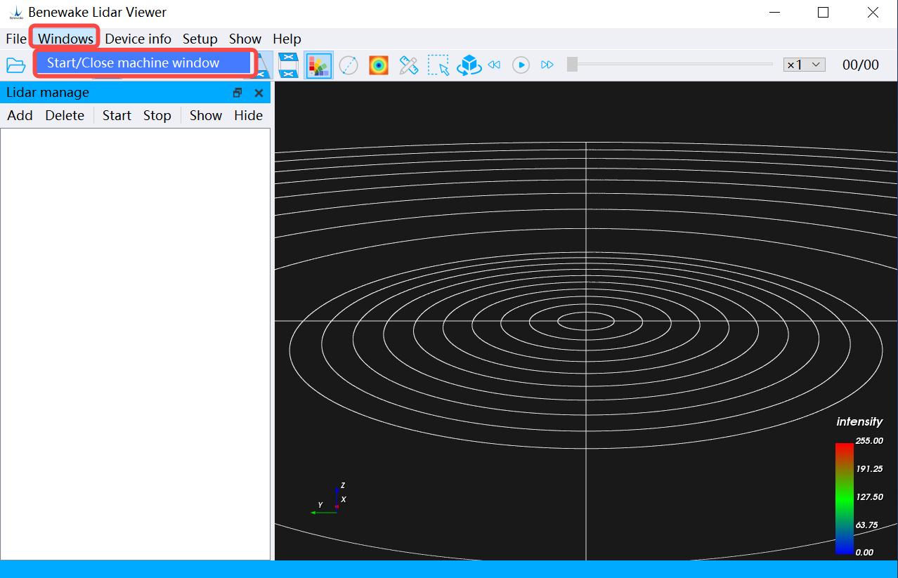
Figure. 30-a: Display device management bar
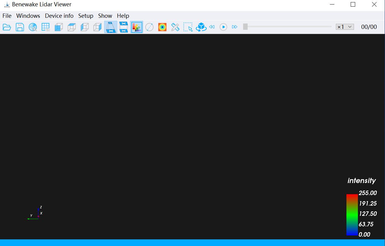
Figure. 30-b: Hide device management bar
4.5.3 Device Information As shown in the figure, click the Menu Bar → Device Information option , and secondary options such as Get Device Information , Get Device Heartbeat Information , Get Device Logs , and Search for Devices in the
© 202 4 Be n ew ak e (B e i ji n g) Co., Ltd. · Al l ri gh t s re se r ve d · RE V: 2 4/03 /20 2 4
Current Network will appear. By clicking these options, you can understand the basic information of the LiDAR device.
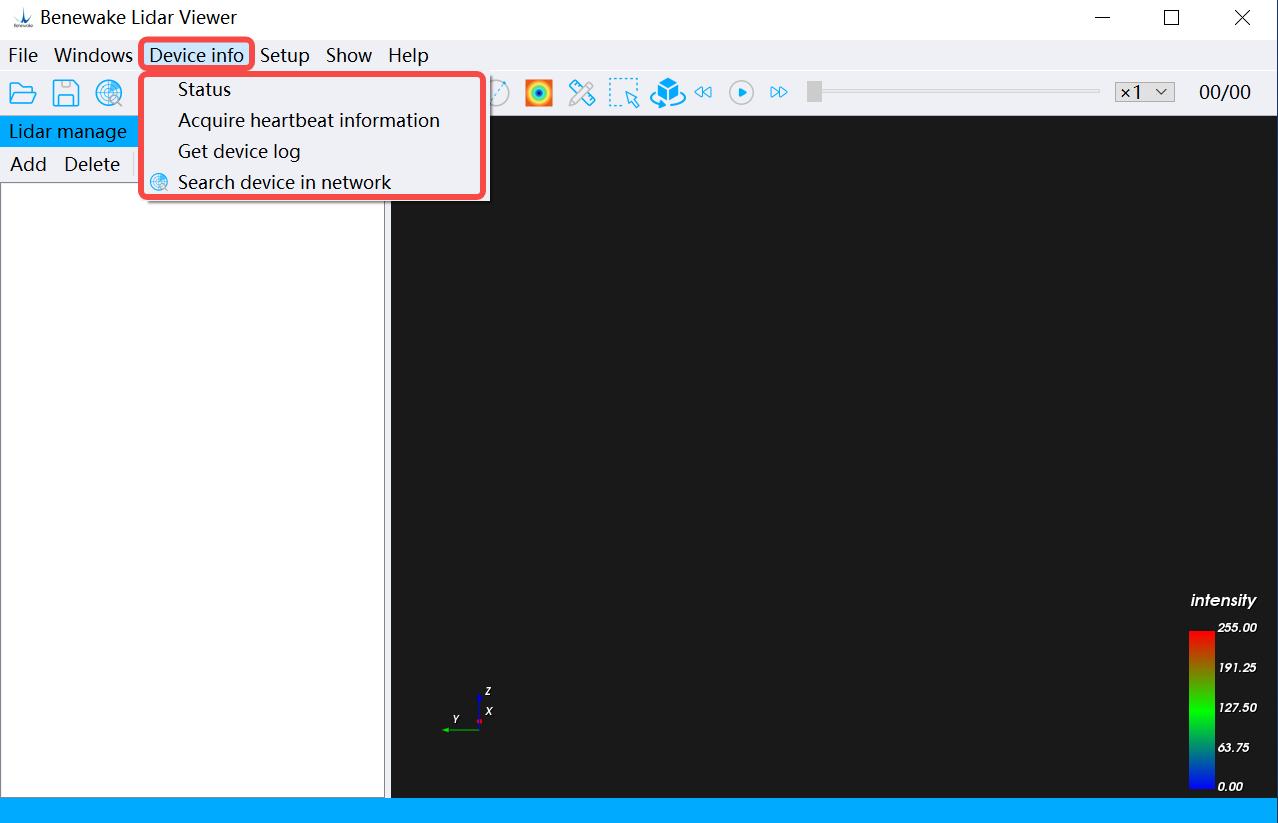
Figure. 31: Device information
1. Get Device Information: The SN number and firmware version of the current device are displayed.
2. Obtain device heartbeat information: The heartbeat signal of the current device can be detected.
3. Get Device Logs: displays the log information of the current device.
4. Search for devices on the current network: Search for radars waiting to connect in the current network segment.
4.5.4 Configuring Device Click the Menu Bar → Configure Device option to configure some functions of the device (Note: If the LiDAR is in the running state, the Configure Device function is not available).
1. Click the Menu Bar → Configure Device → LiDAR Operation Settings → Set Mode options to make the LiDAR operate in different working modes. If you want to know the parameters of each mode, please contact Benewake technical support: su p p o r t @ b e n e w a k e . c o m
© 202 4 Be n ew ak e (B e i ji n g) Co., Ltd. · Al l ri gh t s re se r ve d · RE V: 2 4/03 /20 2 4
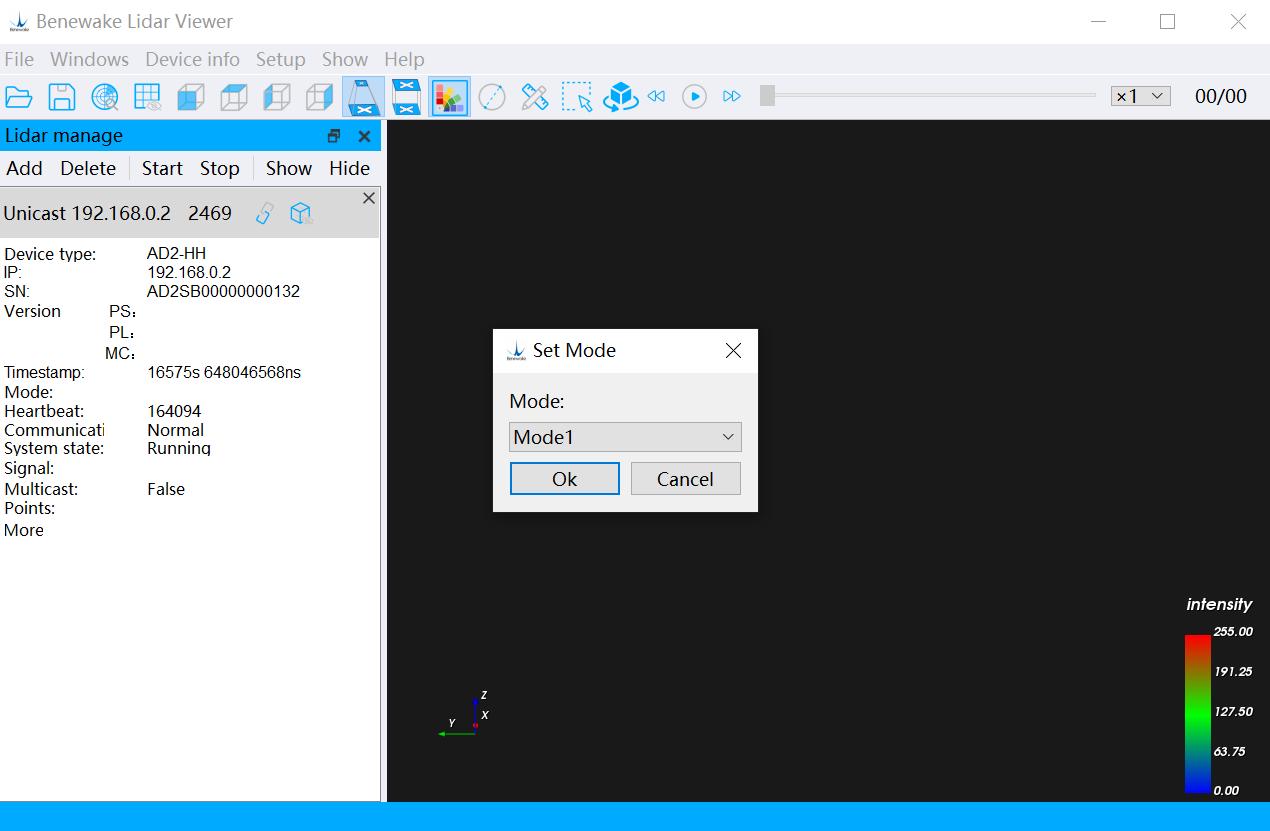
Figure. 32: Setting different modes
2.For other function configurations, please contact Benewake technical support team: su p p o r t @ b e n e w a k e . c o m, and use the sensor under professional guidance. 4.5.5 Point Cloud Display Point cloud display, the main functions are: set the color scheme , set the view , exhibition mode , display color bar , display scale , ranging box selection & 4.4 Chapter . 、 set point size and so on. For more information, please visit 4.1
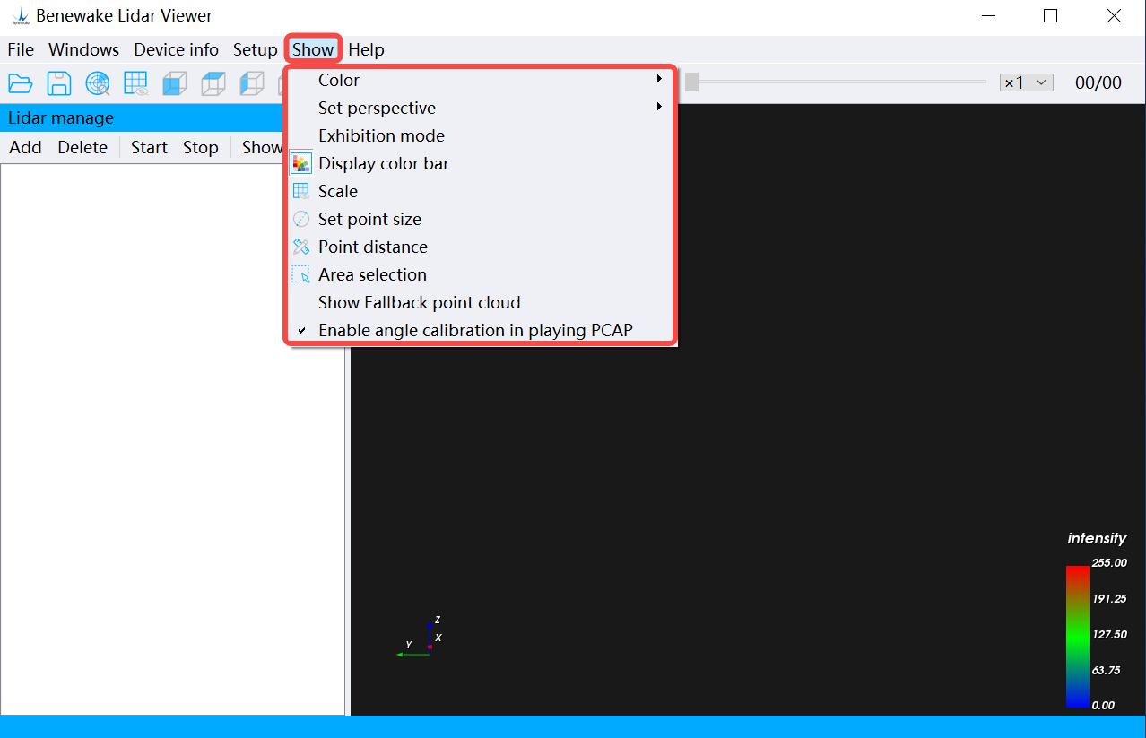
Figure. 33: Point cloud display
© 202 4 Be n ew ak e (B e i ji n g) Co., Ltd. · Al l ri gh t s re se r ve d · RE V: 2 4/03 /20 2 4
4.5.6 Help Menu In addition to the above features, BLV offers a number of other features. Click the Menu Bar → Help option to view.
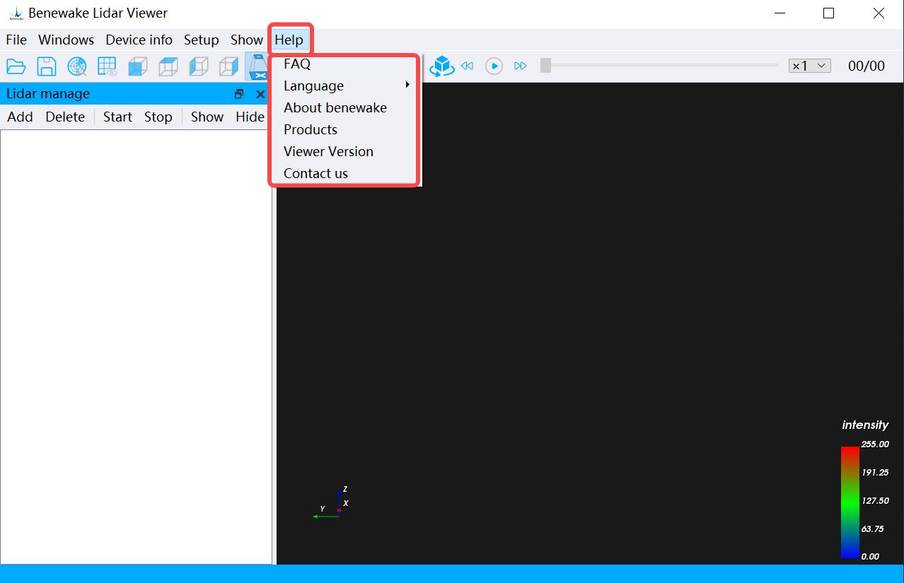
Figure. 34: Help menu
Frequently Asked Questions and Answers: Frequently asked questions and explanations, including: the device does not start, the point cloud is displayed incorrectly or cannot be displayed, etc. Select Language: Select the display language of BLV interface. About Benewake: Company Introduction. Product introduction: Benewake product positioning, application fields, etc., please refer to the product introduction page of the official website for details. Viewer Version: GUI software version and release date. Contact us: If you encounter any problems during use, please contact Benewake technical support.
© 202 4 Be n ew ak e (B e i ji n g) Co., Ltd. · Al l ri gh t s re se r ve d · RE V: 2 4/03 /20 2 4